Page 1802 of 4264
6F – 8 EXHAUST SYSTEM
4JA1TC/4JH1TC
The EGR system engine is controlled by ECM. Refer to “Engine driveability and emissions” section for detail.
RTW46ELF001101
Page 1803 of 4264
EXHAUST SYSTEM 6F – 9
EGR SYSTEM DIAGRAM 4JA1T (L)
RTW46AMF000301
EGR System Operation
Inspect EGR valve motion visually while changing engine RPM under no load condition after warming-up.
Inspection point (Engine RPM)
RPM Idling
900 � 960 2000 3250
Engine Front Side VSV-1 ON ON ON OFF
Engine Rear Side VSV-2 ON OFF ON OFF
ON means VSV should receive signal to move EGR valve.
OFF means VSV shouldn’t receive signal to move EGR valve.
Page 1804 of 4264
6F – 10 EXHAUST SYSTEM
4JA1TC/4JH1TC
The EGR system engine is controlled by ECM. Refer to “Engine driveability and
emissions” section for detail.
RTW46EMF000701
Page 1809 of 4264
EXHAUST SYSTEM 6F – 15
TURBOCHARGER
MAIN DATA AND SPECIFICATIONS
Engine 4JA1T(L) 4JA1TC 4JH1TC
Model IHI RHF4H IHI RHF4H IHI RHF5
Turbine type Mixed type
Compressor type Backword & rake type
Maximum permissible speed rpm 190,000 190,000 180,000
IHI : Ishikawajima Harima Heavy Industries., Ltd.
Page 1810 of 4264
6F – 16 EXHAUST SYSTEM
GENERAL DESCRIPTION
036LV002
The turbocharger internal mechanism consists of the turbine wheel, the compressor wheel, and the radial bearings.
These parts are supported by the bearing housing.
The turbocharger external mechanism consists of the compressor housing air intake port and the turbine housing
air exhaust port.
The turbocharger increases air intake efficiency. This results in increased engine power, reduced fuel consumption,
and minimal engine noise.
The turbocharger operates at very high speeds and temperatures. Part materials have been carefully selected and
machined to extremely high precision.
Turbocharger servicing requires great care and expertise.
If reduced performance is noted, check the engine for damage or wear. If there is no apparent engine damage or
wear, trouble with the turbocharger is indicated.
Page 1811 of 4264

EXHAUST SYSTEM 6F – 17
INSPECTION AND REPAIR
Make the necessary adjustments, repairs, and part replacements if excessive wear or damage is discovered during
inspection.
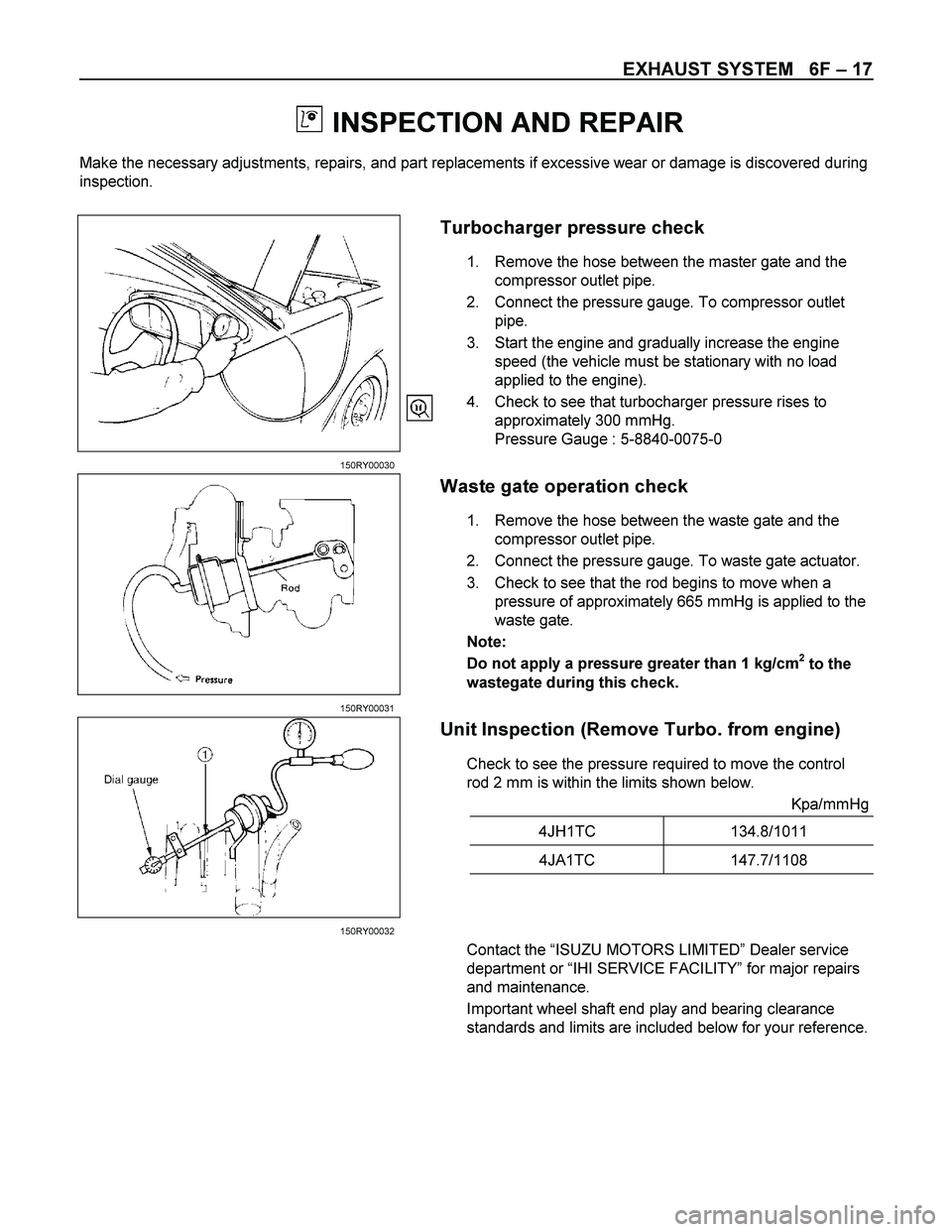
Turbocharger pressure check
1. Remove the hose between the master gate and the
compressor outlet pipe.
2. Connect the pressure gauge. To compressor outlet
pipe.
3. Start the engine and gradually increase the engine
speed (the vehicle must be stationary with no load
applied to the engine).
4. Check to see that turbocharger pressure rises to
approximately 300 mmHg.
Pressure Gauge : 5-8840-0075-0
150RY00030
Waste gate operation check
1. Remove the hose between the waste gate and the
compressor outlet pipe.
2. Connect the pressure gauge. To waste gate actuator.
3. Check to see that the rod begins to move when a
pressure of approximately 665 mmHg is applied to the
waste gate.
Note:
Do not apply a pressure greater than 1 kg/cm
2 to the
wastegate during this check.
150RY00031
Unit Inspection (Remove Turbo. from engine)
Check to see the pressure required to move the control
rod 2 mm is within the limits shown below.
Kpa/mmHg
4JH1TC 134.8/1011
4JA1TC 147.7/1108
150RY00032
Contact the “ISUZU MOTORS LIMITED” Dealer service
department or “IHI SERVICE FACILITY” for major repairs
and maintenance.
Important wheel shaft end play and bearing clearance
standards and limits are included below for your reference.
Page 1820 of 4264

6H – 6 ACCELERATOR CONTROL
RTW46HMH000201
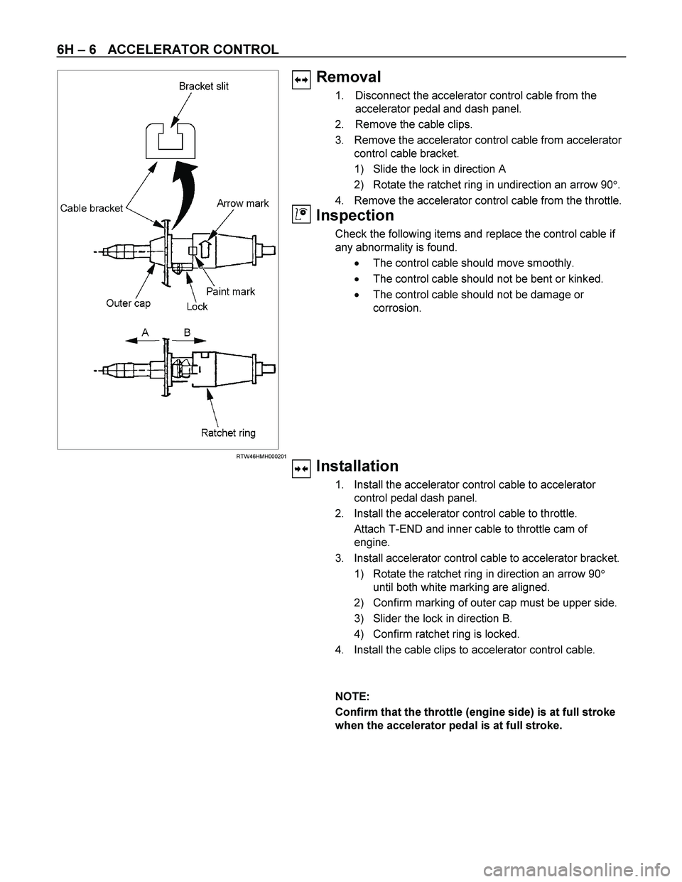
Removal
1. Disconnect the accelerator control cable from the
accelerator pedal and dash panel.
2. Remove the cable clips.
3. Remove the accelerator control cable from accelerator
control cable bracket.
1) Slide the lock in direction A
2) Rotate the ratchet ring in undirection an arrow 90�.
4. Remove the accelerator control cable from the throttle.
Inspection
Check the following items and replace the control cable if
any abnormality is found.
� The control cable should move smoothly.
� The control cable should not be bent or kinked.
� The control cable should not be damage or
corrosion.
Installation
1. Install the accelerator control cable to accelerator
control pedal dash panel.
2. Install the accelerator control cable to throttle.
Attach T-END and inner cable to throttle cam of
engine.
3. Install accelerator control cable to accelerator bracket.
1) Rotate the ratchet ring in direction an arrow 90�
until both white marking are aligned.
2) Confirm marking of outer cap must be upper side.
3) Slider the lock in direction B.
4) Confirm ratchet ring is locked.
4. Install the cable clips to accelerator control cable.
NOTE:
Confirm that the throttle (engine side) is at full stroke
when the accelerator pedal is at full stroke.
Page 1823 of 4264
WORKSHOP MANUAL
TF SERIES
ENGINE
6VE1
SECTION 6