Page 1788 of 4264
6E–416 4JA1/4JH1 ENGINE DRIVEABILITY AND EMISSIONS
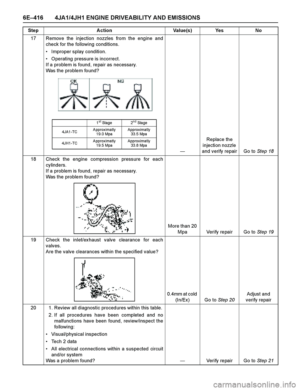
17 Remove the injection nozzles from the engine and
check for the following conditions.
Improper splay condition.
Operating pressure is incorrect.
If a problem is found, repair as necessary.
Was the problem found?
—Replace the
injection nozzle
and verify repair Go to Step 18
18 Check the engine compression pressure for each
cylinders.
If a problem is found, repair as necessary.
Was the problem found?
More than 20
Mpa Verify repair Go to Step 19
19 Check the inlet/ex haust valve clearance for each
valves.
Are the valve clearances within the specified value?
0.4mm at cold
(In/Ex ) Go to Step 20Adjust and
verify repair
20 1. Review all diagnostic procedures within this table.
2. If all procedures have been completed and no
malfunctions have been found, review/inspect the
followi ng:
Visual/physical inspection
Tech 2 data
All electrical connections within a suspected circuit
and/or system
Was a problem found?—Verify repair Go to Step 21 Step Action Value(s) Yes No
1st Stage 2nd Sta ge
4JA1-TCApproximatly
19.0 MpaApprox ima tly
33.5 Mpa
4JH1-TCApproximatly
19.5 MpaApprox ima tly
33.8 Mpa
Page 1789 of 4264
4JA1/4JH1 ENGINE DRIVEABILITY AND EMISSIONS 6E–417
21 Is the ECM programmed with the latest software
release?
If not, download the latest software to the ECM using
the “SPS (Service Programming System)”.
Was the problem solved?—Verify repair Go to Step 22
22 Substitute a known good ECM and recheck.
Was the problem solved?
IMPORTANT: The replacement ECM must be
programmed. Refer to section of the Service
Programming System (SPS) in this manual.
Following ECM programming, the immobilizer system
(if equipped) must be linked to the ECM. Refer to
section 11 “Immobilizer System-ECM replacement” for
the ECM/Immobilizer linking procedure. —Go to Step 24Go to Step 23
23 Replace the ECM.
Is the action complete?
IMPORTANT: The replacement ECM must be
programmed. Refer to section of the Service
Programming System (SPS) in this manual.
Following ECM programming, the immobilizer system
(if equipped) must be linked to the ECM. Refer to
section 11 “Immobilizer System-ECM replacement” for
the ECM/Immobilizer linking procedure.—Veri fy repai r—
24 Replace the injection pump assembly.
Is the action complete?—Veri fy repai r— Step Action Value(s) Yes No
Page 1790 of 4264
6E–418 4JA1/4JH1 ENGINE DRIVEABILITY AND EMISSIONS
ON-VEHICLE SERVICE PROCEDURE
ENGINE CONTROL MODULE
(ECM)
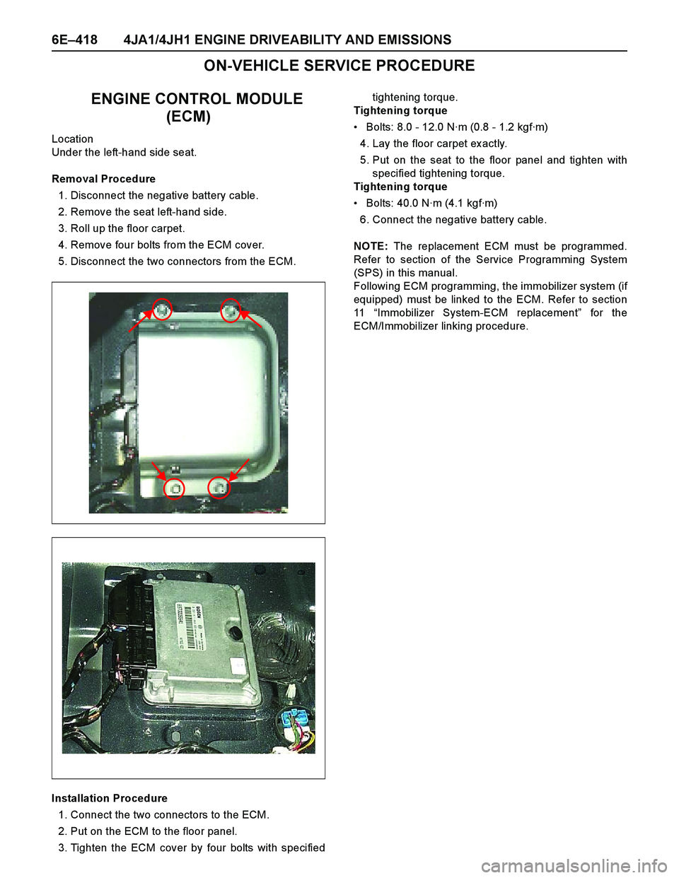
Location
Under the left-hand side seat.
Removal Procedure
1. Disconnect the negative battery cable.
2. Remove the seat left-hand side.
3. Roll up the floor carpet.
4. Remove four bolts from the ECM cover.
5. Disconnect the two connectors from the ECM.
Installation Procedure
1. Connect the two connectors to the ECM.
2. Put on the ECM to the floor panel.
3. Tighten the ECM cover by four bolts with specifiedtightening torque.
Tightening torque
Bolts: 8.0 - 12.0 N·m (0.8 - 1.2 kgf·m)
4. Lay the floor carpet ex actly.
5. Put on the seat to the floor panel and tighten with
specified tightening torque.
Tightening torque
Bolts: 40.0 N·m (4.1 kgf·m)
6. Connect the negative battery cable.
NOTE: The replacement ECM must be programmed.
Refer to section of the Service Programming System
(SPS) in this manual.
Following ECM programming, the immobilizer system (if
equipped) must be linked to the ECM. Refer to section
11 “Immobilizer System-ECM replacement” for the
ECM/Immobilizer linking procedure.
Page 1791 of 4264
4JA1/4JH1 ENGINE DRIVEABILITY AND EMISSIONS 6E–419
CRANKSHAFT POSITION (CKP)
SENSOR
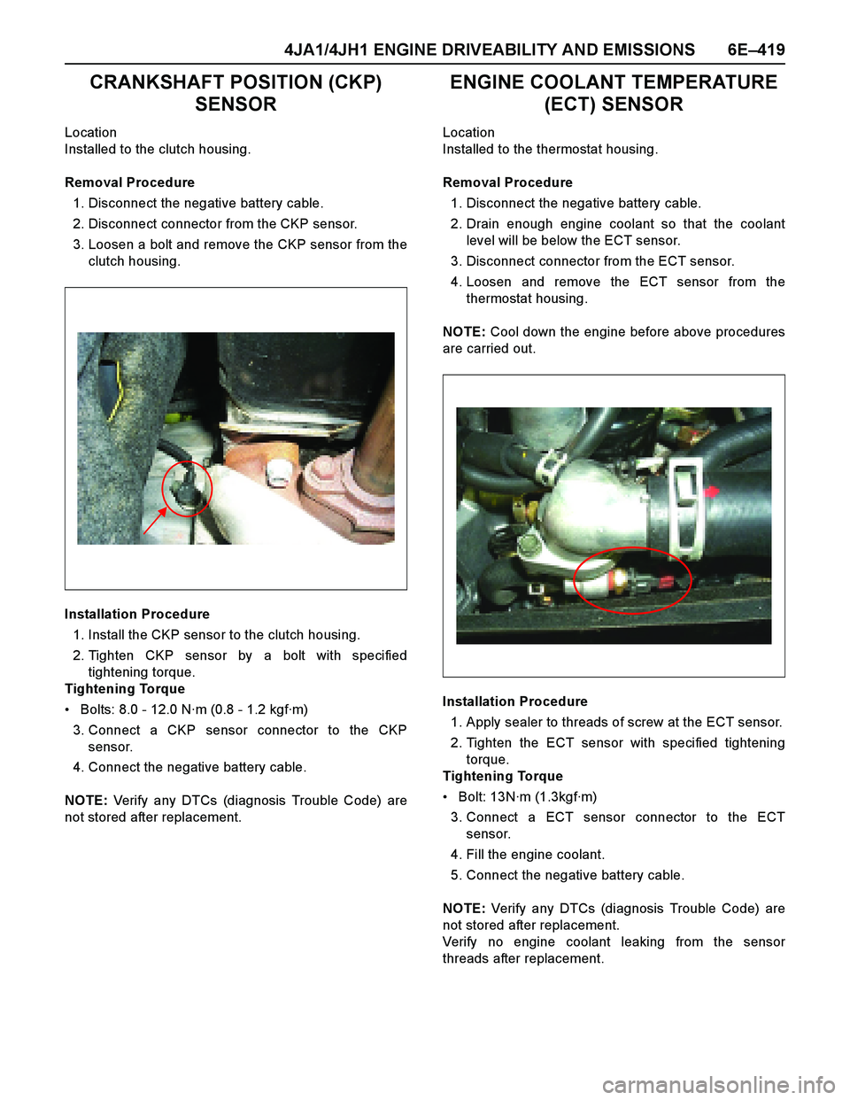
Location
Installed to the clutch housing.
Removal Procedure
1. Disconnect the negative battery cable.
2. Disconnect connector from the CKP sensor.
3. Loosen a bolt and remove the CKP sensor from the
clutch housing.
Installation Procedure
1. Install the CKP sensor to the clutch housing.
2. Tighten CKP sensor by a bolt with specified
tightening torque.
Tightening Torque
Bolts: 8.0 - 12.0 N·m (0.8 - 1.2 kgf·m)
3. Connect a CKP sensor connector to the CKP
sensor.
4. Connect the negative battery cable.
NOTE: Verify any DTCs (diagnosis Trouble Code) are
not stored after replacement.
ENGINE COOLANT TEMPERATURE
(ECT) SENSOR
Location
Installed to the thermostat housing.
Removal Procedure
1. Disconnect the negative battery cable.
2. Drain enough engine coolant so that the coolant
level will be below the ECT sensor.
3. Disconnect connector from the ECT sensor.
4. Loosen and remove the ECT sensor from the
thermostat housing.
NOTE: Cool down the engine before above procedures
are carried out.
Installation Procedure
1. Apply sealer to threads of screw at the ECT sensor.
2. Tighten the ECT sensor with specified tightening
torque.
Tightening Torque
Bolt: 13N·m (1.3kgf·m)
3. Connect a ECT sensor connector to the ECT
sensor.
4. Fill the engine coolant.
5. Connect the negative battery cable.
NOTE: Verify any DTCs (diagnosis Trouble Code) are
not stored after replacement.
Verify no engine coolant leaking from the sensor
threads after replacement.
Page 1792 of 4264
6E–420 4JA1/4JH1 ENGINE DRIVEABILITY AND EMISSIONS
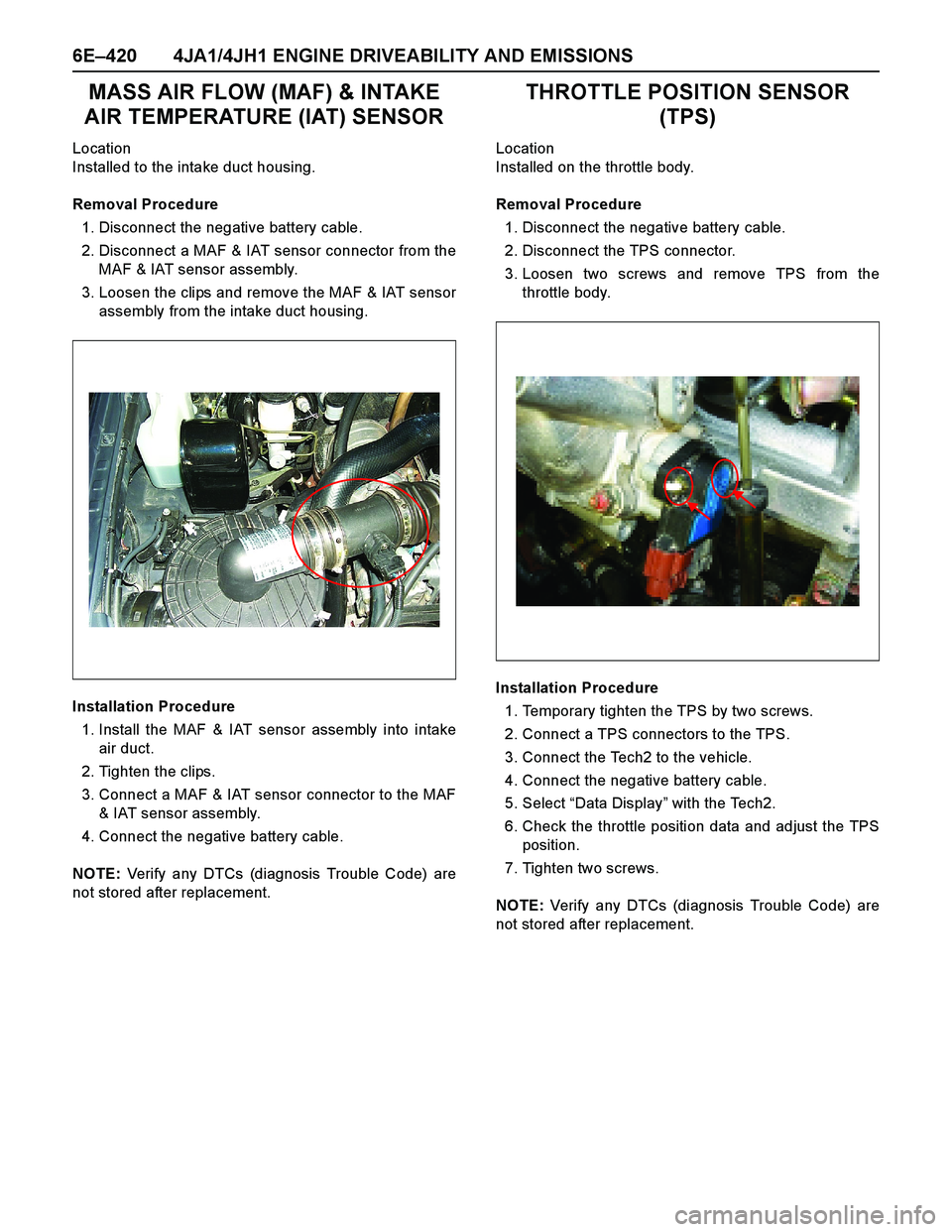
MASS AIR FLOW (MAF) & INTAKE
AIR TEMPERATURE (IAT) SENSOR
Location
Installed to the intake duct housing.
Removal Procedure
1. Disconnect the negative battery cable.
2. Disconnect a MAF & IAT sensor connector from the
MAF & IAT sensor assembly.
3. Loosen the clips and remove the MAF & IAT sensor
assembly from the intake duct housing.
Installation Procedure
1. Install the MAF & IAT sensor assembly into intake
air duct.
2. Tighten the clips.
3. Connect a MAF & IAT sensor connector to the MAF
& IAT sensor assembly.
4. Connect the negative battery cable.
NOTE: Verify any DTCs (diagnosis Trouble Code) are
not stored after replacement.
THROTTLE POSITION SENSOR
(TPS)
Location
Installed on the throttle body.
Removal Procedure
1. Disconnect the negative battery cable.
2. Disconnect the TPS connector.
3. Loosen two screws and remove TPS from the
throttle body.
Installation Procedure
1. Temporary tighten the TPS by two screws.
2. Connect a TPS connectors to the TPS.
3. Connect the Tech2 to the vehicle.
4. Connect the negative battery cable.
5. Select “Data Display” with the Tech2.
6. Check the throttle position data and adjust the TPS
position.
7. Tighten two screws.
NOTE: Verify any DTCs (diagnosis Trouble Code) are
not stored after replacement.
Page 1793 of 4264
4JA1/4JH1 ENGINE DRIVEABILITY AND EMISSIONS 6E–421
EGR EVRV (Electrical Vacuum
Regulating Valve)
Location
Back of the air cleaner case.
Removal Procedure
1. Disconenct the negative battery cable.
2. Disconnect a EVRV connector from the EVRV.
3. Disconnect two hoses from the EVRV.
4. Loosen two bolts and remove the EVRV from the
bracket.
Installation Procedure
1. Tighten the purge solenoid by tow bolts.
2. Connect a connector to the EVRV.
3. Connect two hoses to the EVRV.
4. Connect the negative battery cable.
NOTE: Verify any DTCs (diagnosis Trouble Code) are
not stored after replacement.
Verify proper connection of two hoses.
Page 1794 of 4264
6E–422 4JA1/4JH1 ENGINE DRIVEABILITY AND EMISSIONS
SPECIAL SERVICE TOOLS
ILLUSTRATION TOOL NO.
TOLL NAME
5-8840-0285-0
(J 39200)
High Impedance
Multimeter
(Digital Voltmeter -DVM)
(1) PCMCIA Card
(2) RS232 Loop Back
Connector
(3) SAE 16/19 Adapter
(4) DLC Cable
(5) TECH 2
5-8840-0385-0
(J 35616-A /BT-8637)
Connector Test Adapter Kit
Breaker Box
5-8840-0279-0
(J 23738-A )
Vacuum Pump with Gauge
Page 1801 of 4264
EXHAUST SYSTEM 6F – 7
GENERAL DESCRIPTION
This system controls the formation of NOx emission by recirculating the exhaust gas into the combustion chamber
through the intake manifold.
4JA1T(L):
The two EGR valves are controlled by two Vacuum Switching Valve (VSV) controlled by EGR controller according to
signals from various sensors.
The amount of EGR depends on the number of engine rotations and the opening of the accelerator.
RTW46ELF001201