Page 2680 of 4264
6E–104 ENGINE DRIVEABILITY AND EMISSIONS
Fuel Pressure Relief Procedure
1. Remove the fuel cap.
2. Remove the fuel pump relay from the underhood
relay center.
3. Start the engine and alow it to stall.
4. Crank the engine for an additional 3 seconds.
Fuel Pressure Gauge Installation
1. Remove the fuel pressure fitting cap.
2. Install fuel pressure gauge 5-8840-0378-0 to the
fuel feed line located in front of and above the right
side valve cover.
3. Reinstall the fuel pump relay.
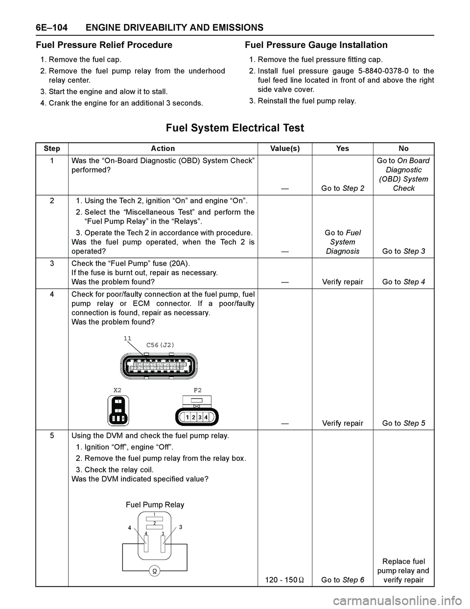
Fuel System Electrical Test
Step Action Value(s) Yes No
1Was the “On-Board Diagnostic (OBD) System Check”
performed?
—Go to Step 2Go to On Board
Diagnostic
(OBD) System
Check
2 1. Using the Tech 2, ignition “On” and engine “On”.
2. Select the “Miscellaneous Test” and perform the
“Fuel Pump Relay” in the “Relays”.
3. Operate the Tech 2 in accordance with procedure.
Was the fuel pump operated, when the Tech 2 is
operated?—Go to Fuel
System
DiagnosisGo to Step 3
3 Check the “Fuel Pump” fuse (20A).
If the fuse is burnt out, repair as necessary.
Was the problem found?—Verify repair Go to Step 4
4 Check for poor/faulty connection at the fuel pump, fuel
pump relay or ECM connector. If a poor/faulty
connection is found, repair as necessary.
Was the problem found?
—Verify repair Go to Step 5
5 Using the DVM and check the fuel pump relay.
1. Ignition “Off”, engine “Off”.
2. Remove the fuel pump relay from the relay box .
3. Check the relay coil.
Was the DVM indicated specified value?
120 - 150�Go to Step 6Replace fuel
pump relay and
verify repair
11C56(J2)
F2 X2
Fuel Pump Relay
� �� �
�
��
Page 2681 of 4264
ENGINE DRIVEABILITY AND EMISSIONS 6E–105
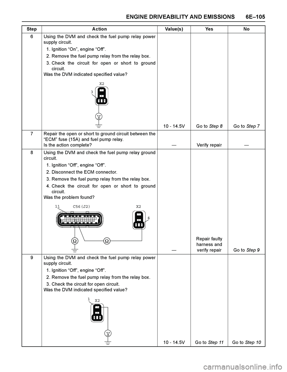
6 Using the DVM and check the fuel pump relay power
supply circuit.
1. Ignition “On”, engine “Off”.
2. Remove the fuel pump relay from the relay box .
3. Check the circuit for open or short to ground
circuit.
Was the DVM indicated specified value?
10 - 14.5V Go to Step 8Go to Step 7
7 Repair the open or short to ground circuit between the
“ECM” fuse (15A) and fuel pump relay.
Is the action complete?—Veri fy repai r—
8 Using the DVM and check the fuel pump relay ground
circuit.
1. Ignition “Off”, engine “Off”.
2. Disconnect the ECM connector.
3. Remove the fuel pump relay from the relay box .
4. Check the circuit for open or short to ground
circuit.
Was the problem found?
—Repair faulty
harness and
verify repair Go to Step 9
9 Using the DVM and check the fuel pump relay power
supply circuit.
1. Ignition “Off”, engine “Off”.
2. Remove the fuel pump relay from the relay box .
3. Check the circuit for open circuit.
Was the DVM indicated specified value?
10 - 14.5V Go to Step 11Go to Step 10 Step Action Value(s) Yes No
V
3
X2
4
11C56(J2) X2
V
1X2
Page 2741 of 4264
ENGINE DRIVEABILITY AND EMISSIONS 6E–165
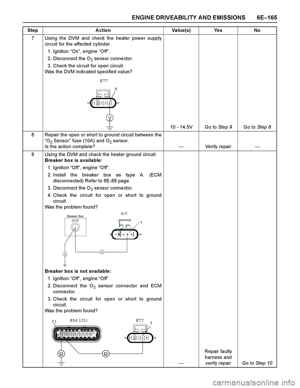
7 Using the DVM and check the heater power supply
circuit for the affected cylinder.
1. Ignition “On”, engine “Off”.
2. Disconnect the O
2 sensor connector.
3. Check the circuit for open circuit.
Was the DVM indicated specified value?
10 - 14.5V Go to Step 9Go to Step 8
8 Repair the open or short to ground circuit between the
“O
2 Sensor” fuse (10A) and O2 sensor.
Is the action complete?—Veri fy repai r—
9 Using the DVM and check the heater ground circuit.
Breaker box is available:
1. Ignition “Off”, engine “Off”.
2. Install the breaker box as type A. (ECM
disconnected) Refer to 6E-88 page.
3. Disconnect the O
2 sensor connector.
4. Check the circuit for open or short to ground
circuit.
Was the problem found?
Breaker box is not available:
1. Ignition “Off”, engine “Off”.
2. Disconnect the O
2 sensor connector and ECM
connector.
3. Check the circuit for open or short to ground
circuit.
Was the problem found?
—Repair faulty
harness and
verify repair Go to Step 10 Step A ction Value(s) Yes No
4
V
E77
J2-31Breaker BoxE-77
�
��
331E56(J2) E77
Page 2769 of 4264
ENGINE DRIVEABILITY AND EMISSIONS 6E–193
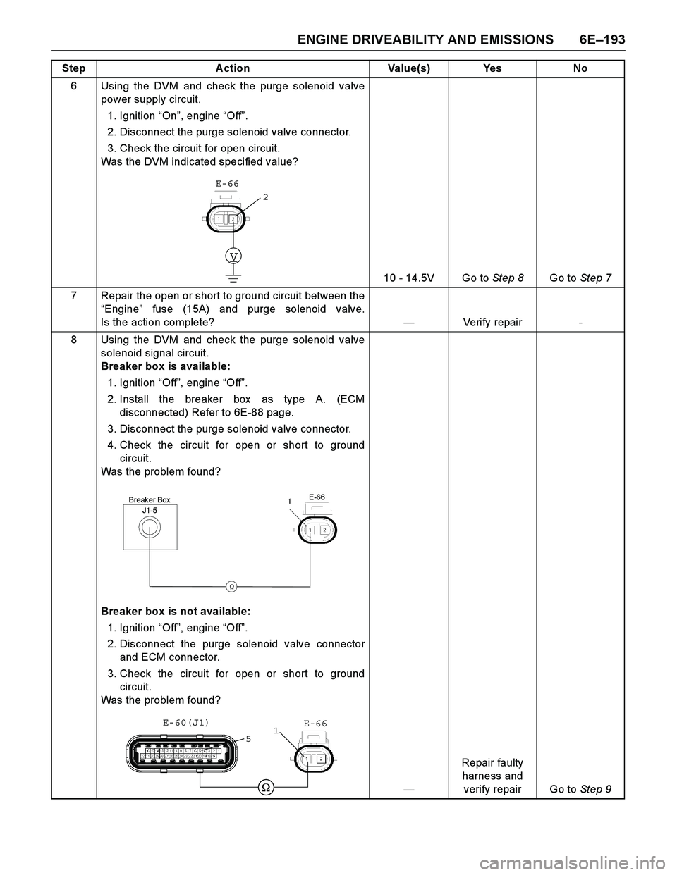
6 Using the DVM and check the purge solenoid valve
power supply circuit.
1. Ignition “On”, engine “Off”.
2. Disconnect the purge solenoid valve connector.
3. Check the circuit for open circuit.
Was the DVM indicated specified value?
10 - 14.5V Go to Step 8Go to Step 7
7 Repair the open or short to ground circuit between the
“Engine” fuse (15A) and purge solenoid valve.
Is the action complete?—Veri fy repai r -
8 Using the DVM and check the purge solenoid valve
solenoid signal circuit.
Breaker box is available:
1. Ignition “Off”, engine “Off”.
2. Install the breaker box as type A. (ECM
disconnected) Refer to 6E-88 page.
3. Disconnect the purge solenoid valve connector.
4. Check the circuit for open or short to ground
circuit.
Was the problem found?
Breaker box is not available:
1. Ignition “Off”, engine “Off”.
2. Disconnect the purge solenoid valve connector
and ECM connector.
3. Check the circuit for open or short to ground
circuit.
Was the problem found?
—Repair faulty
harness and
verify repair Go to Step 9 Step A ction Value(s) Yes No
V
E-66
2
J1-5Breaker BoxE-66
�
�
E-66 E-60(J1)
51
Page 3659 of 4264
TRANSFER CONTROL SYSTEM 7D1-33
No. Connector face No. Connector face
P-2
Silver
Relay & Fuse box
P-5
Silver
Battery (-)
P-6
Silver
Body earth (Ground)
P-10
Silver
Engine ground
P-13
(4JH1)
Gray
Shift on the fly actuator
R-14
Black 2-4WD Control unit
R-15
Black 2-4WD Control unit
Page 3999 of 4264
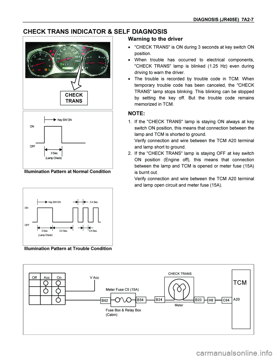
DIAGNOSIS (JR405E) 7A2-7
CHECK TRANS INDICATOR & SELF DIAGNOSIS
CHECK
TRANS
Warning to the driver
� "CHECK TRANS" is ON during 3 seconds at key switch ON
position.
� When trouble has occurred to electrical components,
"CHECK TRANS" lamp is blinked (1.25 Hz) even during
driving to warn the driver.
� The trouble is recorded by trouble code in TCM. When
temporary trouble code has been canceled, the "CHEC
K
TRANS" lamp stops blinking. This blinking can be stopped
by setting the key off. But the trouble code remains
memorized in TCM.
��������Key SW ON
ON
OFF
��
3 Sec.
(Lamp Check)
Illumination Pattern at Normal Condition
NOTE:
1. If the "CHECK TRANS" lamp is staying ON always at key
switch ON position, this means that connection between the
lamp and TCM is shorted to ground.
Verify connection and wire between the TCM A20 terminal
and lamp short to ground.
2. If the "CHECK TRANS" lamp is staying OFF at key switch
ON position (Engine off), this means that connection
between the lamp and TCM is opened or meter fuse (15A)
is burnt out.
Verify connection and wire between the TCM A20 terminal
and lamp open circuit and meter fuse (15A).
��������
Key SW ON 0.4 Sec.
ON
OFF
3 Sec.����
3.2 Sec.����
�
0.4 Sec.
(Lamp Check)
Illumination Pattern at Trouble Condition
Off Acc On V Acc
CHECK TRANS
Meter
Meter Fuse C5 (15A)
Fuse Box & Relay Box
(Cabin)
�
�� �
TCM
������������� ��
��
Page 4024 of 4264
7A2-32 DIAGNOSIS (JR405E)
No. Connector face No. Connector face
E-30
(4JH1-TC)
Gray A/T speed sensor H-23
(6VE1)
(4JH1-TC)
WhiteEngine ~ Engine room B
E-31
(4JH1-TC)
Gray Turbine sensor P-1
SilverBattery (+)
E-44
Gray
Vehicle speed sensor P-2
SilverRelay & Fuse box
E-51
(4JH1-TC)
Black Inhibiter switch P-5
SilverBattery (-)
E-54
(4JH1-TC)
Black A/T term ASM P-6
SilverBody earth (Ground)
H-4
(6VE1)
(4JH1-TC)
White Engine ~ Engine room P-10
SilverEngine ground
H-6
White
Engine room ~ INST R-15
Black2-4 WD control unit
H-7
White
Engine room ~ INST
H-18
(RHD)
White Engine room ~ INST
H-22
(6VE1)
(4JH1-TC)
White Engine ~ Engine room C