Page 2002 of 4264
6E-6 3.5L ENGINE DRIVEABILITY AND EMISSIONS
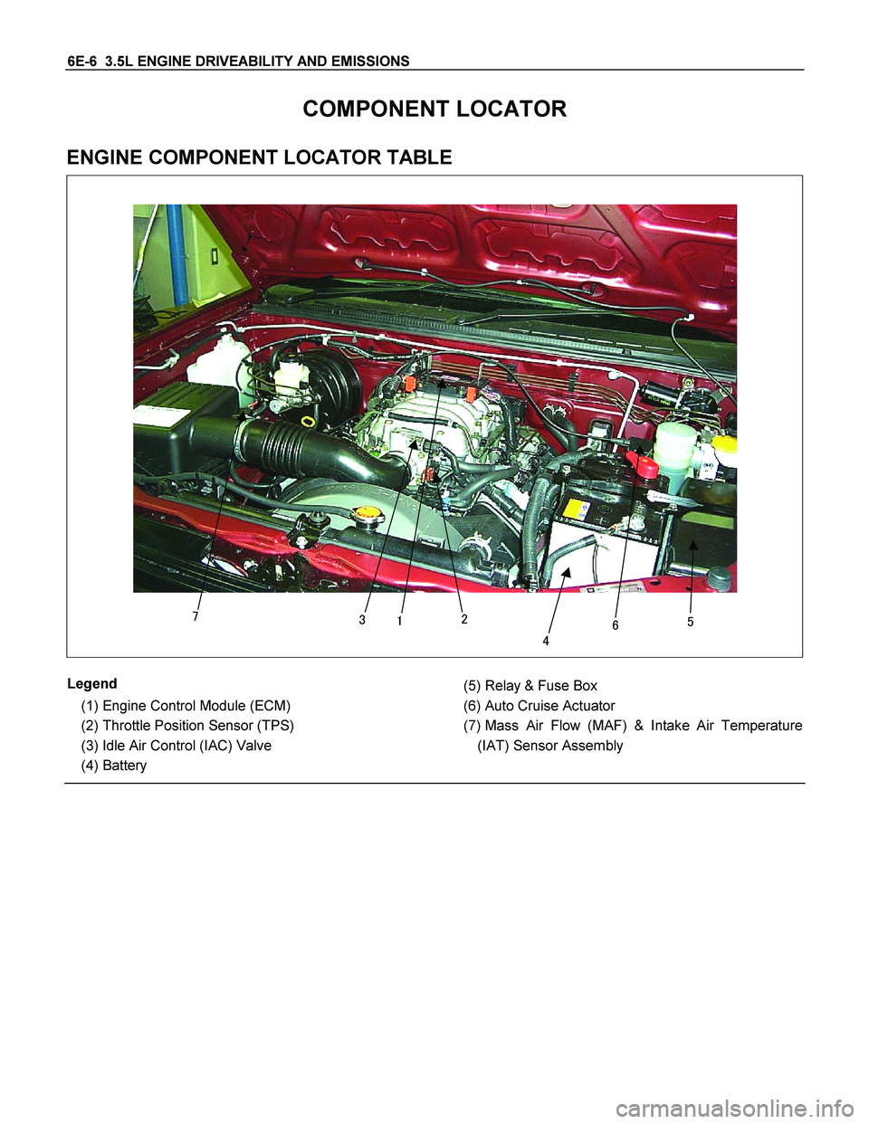
COMPONENT LOCATOR
ENGINE COMPONENT LOCATOR TABLE
�
��� ��
�
Legend
(1) Engine Control Module (ECM)
(2) Throttle Position Sensor (TPS)
(3) Idle Air Control (IAC) Valve
(4) Battery
(5) Relay & Fuse Box
(6) Auto Cruise Actuator
(7) Mass Air Flow (MAF) & Intake Air Temperature
(IAT) Sensor Assembly
Page 2025 of 4264
3.5L ENGINE DRIVEABILITY AND EMISSIONS 6E-29
No. Connector face No. Connector face
E-78
O2 sensor LH-Front P-1
SilverBattery (+)
E-79
Neutral start switch P-2
SilverRelay & Fuse box
F-2
White
Fuel pump & sensor P-5
SilverBattery (-)
H-4
White Engine ~ Engine room P-8
WhiteACG (L)
H-6
White
Engine room ~ INST P-10
SilverEngine ground
H-7
White
Engine room ~ INST X-2
BlackRelay ; Fuel pump
H-9
Blue
Engine room ~ Chassis X-13
BlackRelay ; ECM MAIN
H-18
White
Engine room ~ INST X-14
BlackRelay ; A/C Compressor
H-22
White
Engine ~ Engine room C X-15
BlackRelay ; Thermo
H-23
White Engine ~ Engine room B X-17
BlackDIODE
Page 2026 of 4264
6E-30 3.5L ENGINE DRIVEABILITY AND EMISSIONS
RELAY AND FUSE
RELAY AND FUSE BOX LOCATION (LHD & RHD)
LHD
RHD
RTW48ALF000201 & 825R300008
Page 2027 of 4264
3.5L ENGINE DRIVEABILITY AND EMISSIONS 6E-31
RELAY AND FUSE BOX LOCATION (LHD & RHD)
RELAY & FUSE BOX
RELAY
NO. Relay name
X-1 RELAY; TAIL LIGHT
X-2 RELAY; FUEL PUMP
X-3 RELAY; HORN
X-4 RELAY; DIMMER
X-5 RELAY; FOG LIGHT
X-6 RELAY; STARTER
X-7 RELAY; COND, FAN
X-8 RELAY; �
X-9 RELAY; HAZARD-RH
X-10 RELAY; HAZARD-LH
X-11 RELAY; HEATER
X-12 RELAY; HEAD LIGHT
X-13 RELAY; ECM MAIN
X-14 RELAY; A/C COMP
X-15 RELAY; THERMO
FUSE
�������� �
���
���
����� ���������
����� �������������
����� ���������
����� �������������
����� ������ ����
���!� �������� �
��������� �
�����
����������"���������� �
����������
��������� �
�����
����������#���������� �
����������
���$� ���������������
������ �������� �%��%�
��������
��������
������ ������&��
������ ������'(�
������ �����)����
����!� �����)�*��(�
SLOW BLOW FUSE
�������� �+,-��+,-��
���
���
������ �����������
��������
��������
������ ���������(.�����
������ �����������
����!� �����������
����"� �����������
����#� ������ �'���
����$� ����������
Page 2028 of 4264
6E-32 3.5L ENGINE DRIVEABILITY AND EMISSIONS
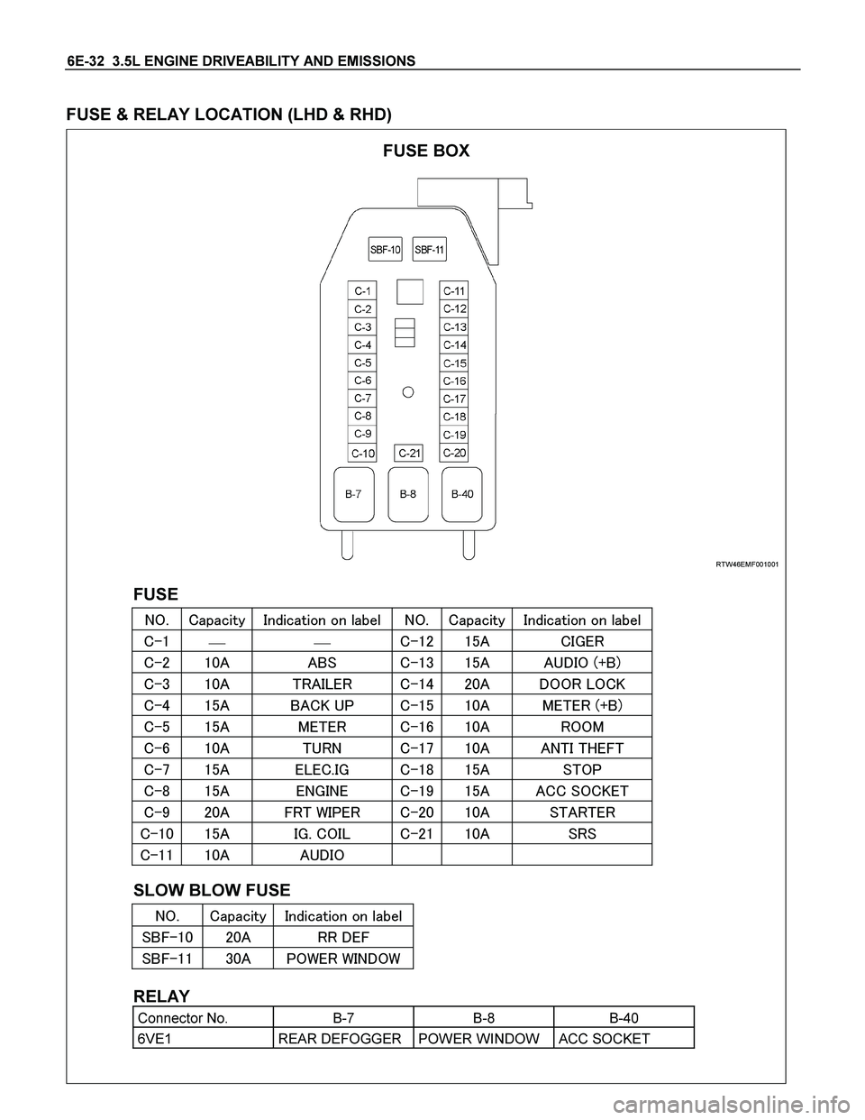
FUSE & RELAY LOCATION (LHD & RHD)
RTW46EMF001001
FUSE
���� �
/
0123� ��410
21,��,��+
5�+ ��� �
/
0123 ��410
21,��,��+
5�+�
����
�������� ���� ������
���� ���� ���� ���� ���� ��(����6���
���� ���� ���� ��� ���� ���� (���� ��7�
���� ���� ���7��%� ���� ���� �������6���
���� ���� ������ ���! ���� �����
��!� ���� ����� ���" ���� ������)����
��"� ���� � ������ ���# ���� ���%�
��#� ���� ������� ���$ ���� �������7���
��$� ���� ����'�%��� ���� ���� ��������
����� ���� ������� � ���� ���� ����
����� ���� ��(��� � � �
SLOW BLOW FUSE
���� �
/
0123� ��410
21,��,��+
5�+
������� ���� ���(���
������� ���� %�'���'��(�'�
RELAY
Connector No. B-7 B-8 B-40
6VE1 REAR DEFOGGER POWER WINDOW ACC SOCKET
FUSE BOX
Page 2060 of 4264

6E-64 3.5L ENGINE DRIVEABILITY AND EMISSIONS
Diagnostic Thought Process
As you follow a diagnostic plan, every box on the
Strategy Based Diagnostics chart requires you to use
the diagnostic thought process. This method of thinking
optimizes your diagnosis in the following ways:
� Improves your understanding and definition of the
customer complaint
� Saves time by avoiding testing and/or replacing
good parts
�
Allows you to look at the problem from different
perspectives
� Guides you to determine what level o
f
understanding about system operation is needed:
� Owner’s manual level
� Service manual level
� In-depth (engineering) level
1. Verify the Complaint
What you should do
To verify the customer complaint, you need to know the
correct (normal) operating behavior of the system and
verify that the customer complaint is a valid failure o
f
the system.
The following information will help you verify the
complaint:
� WHAT the vehicle model/options are
� WHAT aftermarket and dealer-installed
accessories exist
� WHAT related system(s) operate properly
� WHEN the problem occurs
� WHERE the problem occurs
� HOW the problem occurs
� HOW LONG the condition has existed (and if the
system ever worked correctly)
� HOW OFTEN the problem occurs
� Whether the severity of the problem has
increased, decreased or stayed the same
What resources you should use
Whenever possible, you should use the following
resources to assist you in verifying the complaint:
Service manual Theory or Circuit Description
sections
� Service manual “System Performance Check”
� Owner manual operational description
� Technician experience
� Identical vehicle for comparison
� Circuit testing tools
� Vehicle road tests
� Complaint check sheet
� Contact with the customer
2. Perform Preliminary Checks
NOTE: An estimated 10 percent of successful
vehicle repairs are diagnosed with this step!
What you should do
You perform preliminary checks for several reasons:
� To detect if the cause of the complaint is
VISUALLY OBVIOUS
� To identify parts of the system that work correctly
� To accumulate enough data to correctly and
accurately search for a ISUZU Service Bulletin.
The initial checks may vary depending on the
complexity of the system and may include the following
actions:
� Operate the suspect system
� Make a visual inspection of harness routing and
accessible/visible power and ground circuits
� Check for blown fuses
� Make a visual inspection for separated connectors
� Make a visual inspection of connectors (includes
checking terminals for damage and tightness)
� Check for any DTCs stored by the on-board
computers
� Sense unusual noises, smells, vibrations o
r
movements
� Investigate the vehicle service history (call othe
r
dealerships, if appropriate)
What resources you should use
Whenever appropriate, you should use the following
resources for assistance in performing preliminary
checks:
� Tech 2 or other technical equipment for viewing
DTCs
� Service manual information:
� Component locations
� Harness routing
� Wiring schematics
� Procedures for viewing DTCs
� Dealership service history file
� Vehicle road test
� Identical vehicle or system for comparison
Page 2109 of 4264
 Yes No
5
Using the DVM and check the fuel pump relay.
1. Ignition \"Off\", engine \"Off\".
2. Remove the fuel pump relay")
3.5L ENGINE DRIVEABILITY AND EMISSIONS 6E-113
Step Action Value (s) Yes No
5
Using the DVM and check the fuel pump relay.
1. Ignition "Off", engine "Off".
2. Remove the fuel pump relay from the relay box.
3. Check the relay coil.
Was the DVM indicated specified value?
X-2
�
1
3 2
4
�
��
Approximately
140�
Go to Step 6 Replace fuel
pump relay and
verify repair
6
Using the DVM and check the fuel pump relay power
supply circuit.
1. Ignition "On", engine "Off".
2. Remove the fuel pump relay from the relay box.
3. Check the circuit for open or short to ground circuit.
Was the DVM indicated specified value?
X-2
�
V
�
10 – 14.5V Go to Step 8 Go to Step 7
7
Repair the open or short to ground circuit between the
"ECM" fuse (15A) and fuel pump relay.
Is the action complete?
- Verify repair -
8
Using the DVM and check the fuel pump relay ground
circuit.
1. Ignition "Off", engine "Off".
2. Disconnect the ECM connector.
3. Remove the fuel pump relay from the relay box.
4. Check the circuit for open or short to ground circuit.
Was the problem found?
E-61(B)
X-2
�
�
�
�
��
- Repair faulty
harness and
verify repair Go to Step 9
Page 2120 of 4264
 Yes No
8
Check for poor/faulty connection at the A/C
compressor, A/C compressor relay or ECM connector.
If a poor/faulty c")
6E-124 3.5L ENGINE DRIVEABILITY AND EMISSIONS
Step Action Value (s) Yes No
8
Check for poor/faulty connection at the A/C
compressor, A/C compressor relay or ECM connector.
If a poor/faulty connection is found, repair as
necessary.
Was the problem found?
E-2
�
X-14
�
�
�
�
�
E-61(B)��
- Verify repair Go to Step 9
9
� Using the DVM and check the A/C compressor relay.
1. Ignition "Off", engine "Off".
2. Remove the A/C compressor relay from the relay
box.
3. Check the relay coil.
Was the DVM indicated specified value?
X-14
���
�
Approximately
140�
Go to Step 10 Replace A/C
compressor relay
and verify repair
10
Using the DVM and check the A/C compressor relay
power supply circuit.
1. Ignition "On", engine "Off".
2. Remove the A/C compressor relay from the relay
box.
3. Check the circuit for open or short to ground circuit.
Was the DVM indicated specified value?
X-14
�
�
�
VV
10 – 14.5V Go to Step 12 Go to Step 11
11
Repair the open or short to ground circuit between the
"A/C" fuse (10A) and A/C compressor relay.
Is the action complete?
- Verify repair -

E-79
Neutral start switch P-2
SilverRelay & Fuse bo")

LHD
RHD
RTW48ALF000201 & 825R300008")

RELAY & FUSE BOX
RELAY
NO. Relay name
X-1 RELAY; TAIL LIGHT
X-2 RELAY; FUEL PUMP
X-3 RELAY; HORN
X-4")