Page 829 of 4264
ELECTRICAL-BODY AND CHASSIS 8A-171
HORN
1. Both sides of horn do not sound
Checkpoint Trouble Cause Countermeasure
Repair the grounding point
Poor ground contact
NG
Horn relay
Grounding point
Reinstall or replace fuse No.
EB-15 (10A)
Fuse No EB-15 (10A, Relay
and fuse box)
Poor fuse contact or blown
fuse
NG
OK OK
Reinstall or replace the horn
relay
Poor relay contact or faulty
horn relay
NG
Voltage between connector
3
X-3 - ground or 1 X-3
- ground (Should be battery
voltage present) OK
Repair open circuit or
reconnect the connector
Open circuit or poor connector
contact between fuse No. EB-
15 (10A) and horn relay
NG
Remove steering pad and
steering wheel
OK
Horn switch continuity
OK
Repair or replace the horn
switch
Poor switch point contact or
faulty switch
NG
Continuity between
4
X-3 - 10 B-60
2
X-3 - 1 C-20 (1 C-21) OK
Repair open circuit or
connector contact
Open circuit or poor connector
contact
NG
Page 961 of 4264
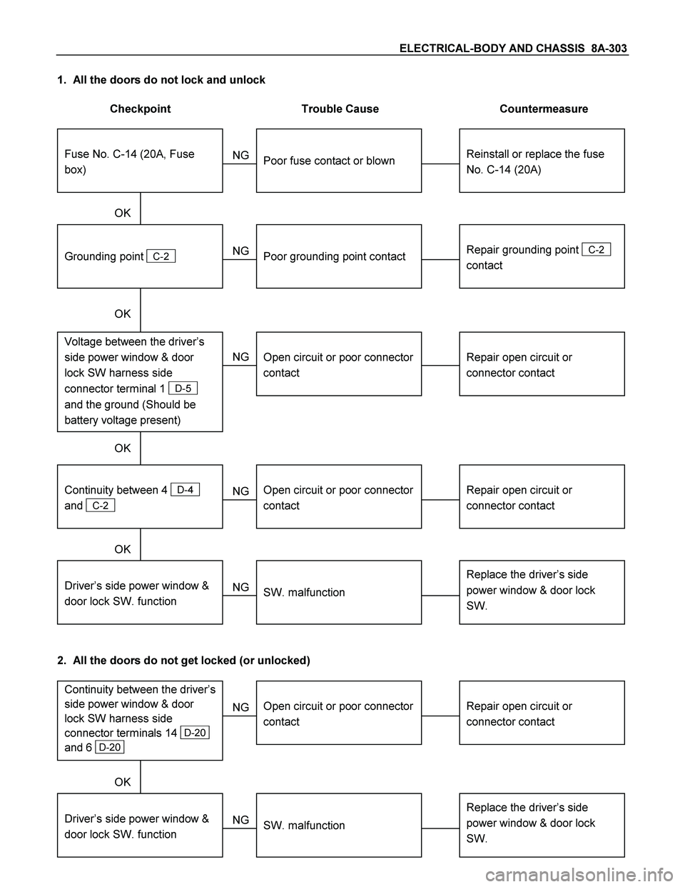
ELECTRICAL-BODY AND CHASSIS 8A-303
1. All the doors do not lock and unlock
Checkpoint Trouble Cause Countermeasure
Reinstall or replace the fuse
No. C-14 (20A)
Poor fuse contact or blown
NG
Repair grounding point
C-2
contact
Grounding point
C-2
Poor grounding point contact
Repair open circuit or
connector contact
Voltage between the driver’s
side power window & door
lock SW harness side
connector terminal 1
D-5
and the ground (Should be
battery voltage present)
Open circuit or poor connector
contact
NG NG OK
OK OK
Fuse No. C-14 (20A, Fuse
box)
Repair open circuit or
connector contact
Open circuit or poor connector
contact
NG
Replace the driver’s side
power window & door lock
SW.
Driver’s side power window &
door lock SW. function
SW. malfunction
NG OK
Continuity between 4
D-4
and
C-2
2. All the doors do not get locked (or unlocked)
Repair open circuit or
connector contact
Open circuit or poor connector
contact
NG
Replace the driver’s side
power window & door lock
SW.
Driver’s side power window &
door lock SW. function
SW. malfunction
NG OK
Continuity between the driver’s
side power window & door
lock SW harness side
connector terminals 14
D-20
and 6
D-20
Page 975 of 4264
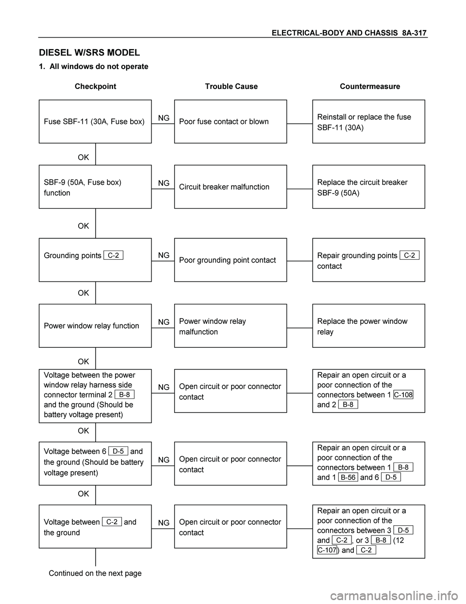
ELECTRICAL-BODY AND CHASSIS 8A-317
DIESEL W/SRS MODEL
1. All windows do not operate
Checkpoint Trouble Cause Countermeasure
Reinstall or replace the fuse
SBF-11 (30A)
Poor fuse contact or blown
NG
Replace the circuit breaker
SBF-9 (50A)
SBF-9 (50A, Fuse box)
function
Circuit breaker malfunction
Repair grounding points
C-2
contact
Grounding points
C-2
Poor grounding point contact
NG NG OK
OK OK
Fuse SBF-11 (30A, Fuse box)
Replace the power window
relay
Power window relay
malfunction
NG
Repair an open circuit or a
poor connection of the
connectors between 1
C-108
and 2
B-8
Voltage between the power
window relay harness side
connector terminal 2
B-8
and the ground (Should be
battery voltage present)
Open circuit or poor connector
contact
NG OK
Power window relay function
OK
Repair an open circuit or a
poor connection of the
connectors between 1
B-8
and 1
B-56 and 6 D-5
Open circuit or poor connector
contact
NG Voltage between 6 D-5 and
the ground (Should be battery
voltage present)
OK
Repair an open circuit or a
poor connection of the
connectors between 3
D-5
and
C-2 , or 3 B-8 (12
C-107 )
and C-2
Open circuit or poor connector
contact
NG
Continued on the next page
Voltage between
C-2 and
the ground
Page 993 of 4264
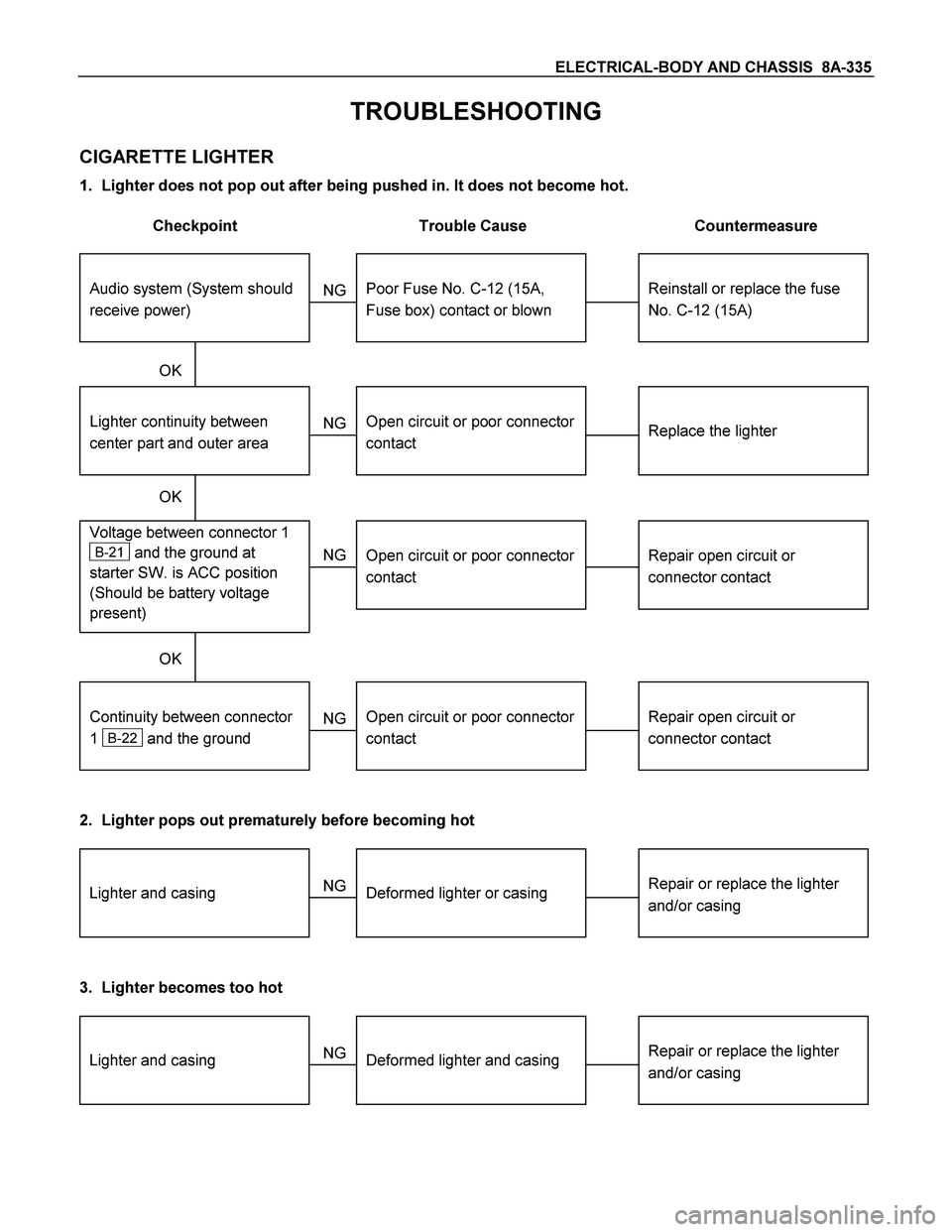
ELECTRICAL-BODY AND CHASSIS 8A-335
TROUBLESHOOTING
CIGARETTE LIGHTER
1. Lighter does not pop out after being pushed in. It does not become hot.
Checkpoint Trouble Cause Countermeasure
Reinstall or replace the fuse
No. C-12 (15A)
Poor Fuse No. C-12 (15A,
Fuse box) contact or blown
NG
Replace the lighter
Lighter continuity between
center part and outer area
Open circuit or poor connector
contact
Repair open circuit or
connector contact
Voltage between connector 1
B-21 and the ground at
starter SW. is ACC position
(Should be battery voltage
present)
Open circuit or poor connector
contact
NG NG OK
OK OK
Audio system (System should
receive power)
Repair open circuit or
connector contact
Open circuit or poor connector
contact
NG
Continuity between connector
1
B-22 and the ground
2. Lighter pops out prematurely before becoming hot
Repair or replace the lighter
and/or casingDeformed lighter or casing NGLighter and casing
3. Lighter becomes too hot
Repair or replace the lighter
and/or casingDeformed lighter and casing NGLighter and casing
Page 1000 of 4264
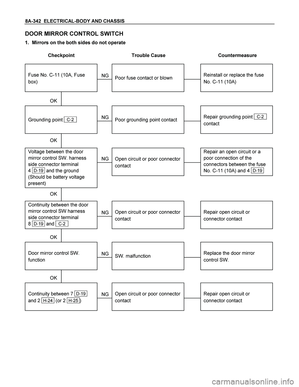
8A-342 ELECTRICAL-BODY AND CHASSIS
DOOR MIRROR CONTROL SWITCH
1. Mirrors on the both sides do not operate
Checkpoint Trouble Cause Countermeasure
Reinstall or replace the fuse
No. C-11 (10A)
Poor fuse contact or blown
NG
Repair grounding point
C-2
contact
Grounding point
C-2
Poor grounding point contact
Repair an open circuit or a
poor connection of the
connectors between the fuse
No. C-11 (10A) and 4
D-19
Voltage between the door
mirror control SW. harness
side connector terminal
4
D-19 and the ground
(Should be battery voltage
present)
Open circuit or poor connector
contact
NG NG OK
OK OK
Fuse No. C-11 (10A, Fuse
box)
Repair open circuit or
connector contact
Open circuit or poor connector
contact
NG Continuity between the door
mirror control SW harness
side connector terminal
8
D-19 and C-2
Replace the door mirror
control SW.
Door mirror control SW.
function
SW. malfunction
NG OK
Repair open circuit or
connector contact
Continuity between 7
D-19
and 2
H-24 (or 2 H-25 )
Open circuit or poor connector
contact
NG OK
Page 1011 of 4264
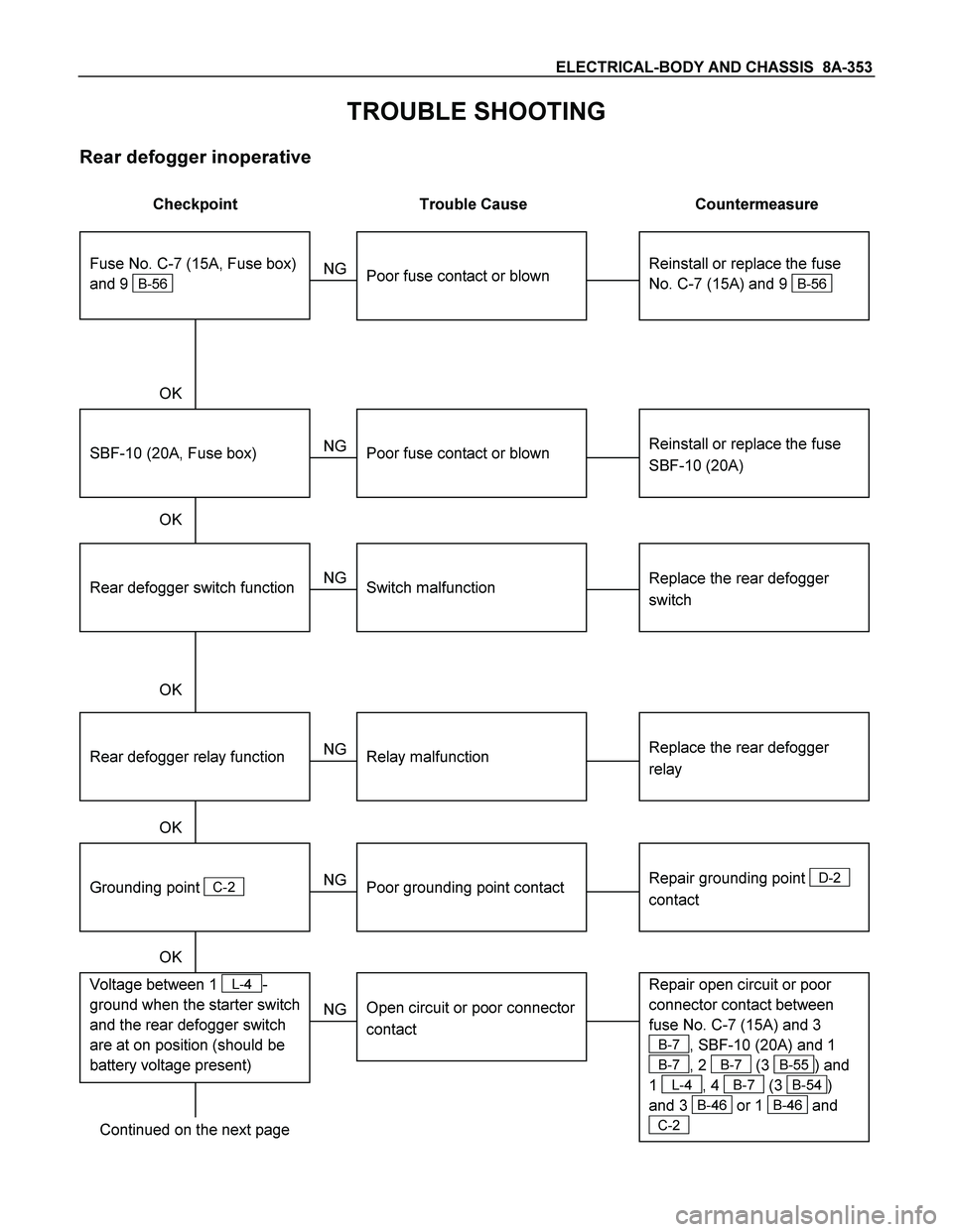
ELECTRICAL-BODY AND CHASSIS 8A-353
TROUBLE SHOOTING
Rear defogger inoperative
Checkpoint Trouble Cause Countermeasure
Reinstall or replace the fuse
No. C-7 (15A) and 9
B-56
Poor fuse contact or blown
NG
Reinstall or replace the fuse
SBF-10 (20A)
SBF-10 (20A, Fuse box)
Poor fuse contact or blown
Replace the rear defogger
switch
Rear defogger switch function
Switch malfunction
NG NG OK
OK OK
Fuse No. C-7 (15A, Fuse box)
and 9
B-56
Replace the rear defogger
relay
Relay malfunction
NG
Continued on the next page
Rear defogger relay function
Repair grounding point
D-2
contact
Grounding point
C-2
Poor grounding point contact
NG OK
Repair open circuit or poor
connector contact between
fuse No. C-7 (15A) and 3
B-7, SBF-10 (20A) and 1
B-7, 2 B-7 (3 B-55) and
1
L-4, 4 B-7 (3 B-54)
and 3
B-46 or 1 B-46 and
C-2
Voltage between 1 L-4-
ground when the starter switch
and the rear defogger switch
are at on position (should be
battery voltage present)
Open circuit or poor connector
contact
NG OK
Page 1095 of 4264
ELECTRICAL-BODY AND CHASSIS 8A-437
No. Connector face No. Connector face
P-1
Silver
Battery (+) P-9
SilverACG (B)
P-2
Silver
Relay & Fuse box P-10
SilverEngine ground
P-3
Brown
Starter (S) P-11
SilverFuse & relay box
P-4
Silver
Starter (B) P-12
NOT USED
P-4
Silver
Starter (B) P-13
Gray Shift on the fly actuator
P-5
Silver
Battery (-) P-14
WhiteFuse & relay box
P-6
Silver
Body earth (Ground) P-15
Silver2nd battery (+)
P-7
NOT USED P-16
Silver
2nd battey (-)
P-8
(C24SE)
(4JH1-TC
Green ACG (L)
P-8
(6VE1)
White ACG (L)
Page 1371 of 4264
ENGINE ELECTRICAL 6D – 33
PRE-HEATING SYSTEM
INSPECTION AND REPAIR
Make the necessary adjustments, repairs, and part replacement if excessive wear of damage is discovered during
inspection.
VISUAL CHECK
Check the main fuses and glow indicator for damage.
Replace the part(s) if required.
GLOW RELAY
The glow relay is located in the relay box the engine
compartment.
825R300046
Use an ohmmeter to measure the resistance between
terminals No.2 and No.3.
If the measured value is outside the specified range, the
glow relay must be replaced.
Glow Relay Resistance Ohms
94 � 114
GLOW PLUG
LNW21KSH001401
Use a circuit tester to test the glow plugs for continuity.
Glow Plug Resistance (Reference) Ohms
Approximately 0.9
EGR SYSTEM 4JA1T (L)
Refer to 6F-9. (EGR system diagram)