Page 3000 of 4264

0B-12 MAINTENANCE AND LUBRICATION
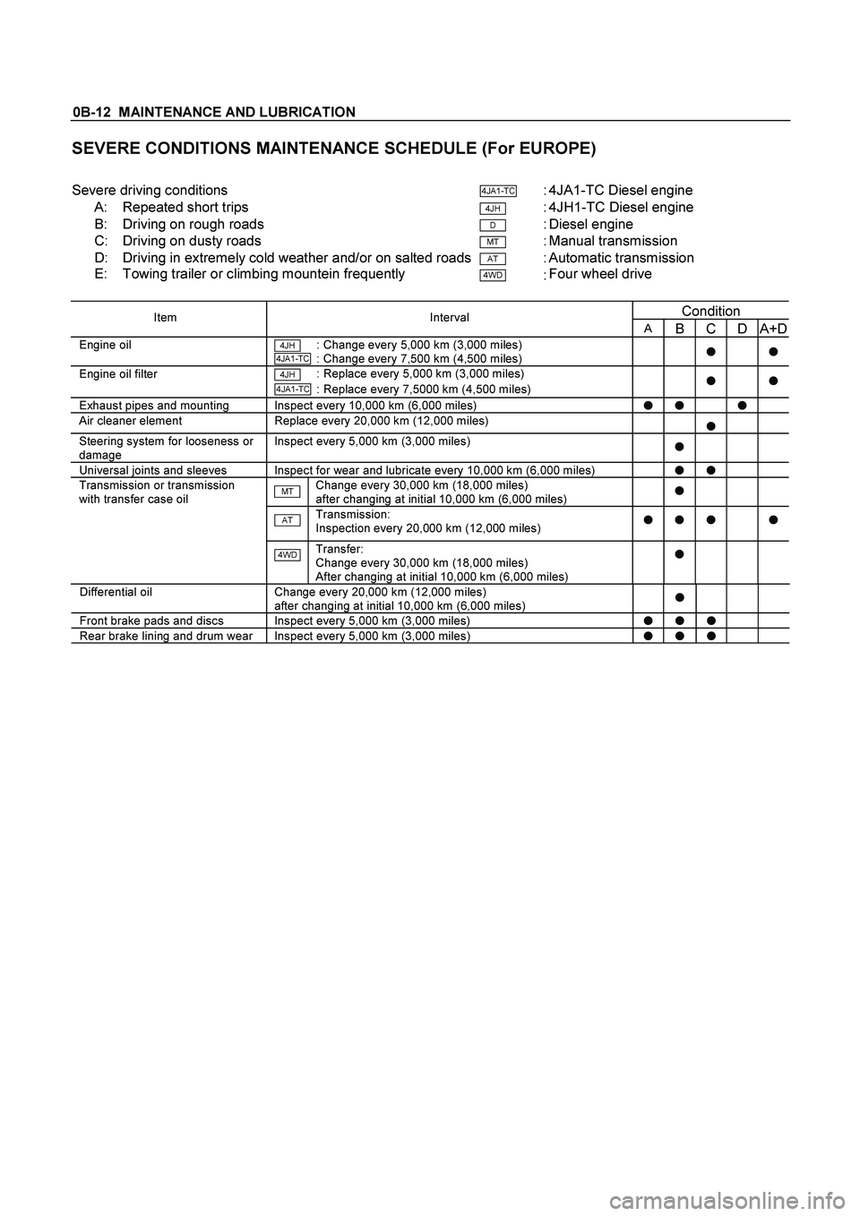
SEVERE CONDITIONS MAINTENANCE SCHEDULE (For EUROPE)
�
Severe driving conditions
4JA1-TC : 4JA1-TC Diesel engine
A: Repeated short trips
4JH : 4JH1-TC Diesel engine
B: Driving on rough roads
D : Diesel engine
C: Driving on dusty roads
MT : Manual transmission
D: Driving in extremely cold weather and/or on salted roads
AT : Automatic transmission
E: Towing trailer or climbing mountein frequently
4WD : Four wheel drive
�
Condition
Item Interval
A B C D A+D
Engine oil 4JH : Change every 5,000 km (3,000 miles) 4JA1-TC : Change every 7,500 km (4,500 miles)
�
�Engine oil filter 4JH : Replace every 5,000 km (3,000 miles) 4JA1-TC : Replace every 7,5000 km (4,500 miles)
�
�
Exhaust pipes and mounting Inspect every 10,000 km (6,000 miles)
� �
�
Air cleaner element Replace every 20,000 km (12,000 miles)
�
Steering system for looseness or
damage Inspect every 5,000 km (3,000 miles)
�
Universal joints and sleeves Inspect for wear and lubricate every 10,000 km (6,000 miles)
� �
Transmission or transmission
with transfer case oil MT Change every 30,000 km (18,000 miles)
after changing at initial 10,000 km (6,000 miles)
�
AT
Transmission:
Inspection every 20,000 km (12,000 miles) � � �
�
4WD Transfer:
Change every 30,000 km (18,000 miles)
After changing at initial 10,000 km (6,000 miles)
�
Differential oil Change every 20,000 km (12,000 miles)
after changing at initial 10,000 km (6,000 miles)
�
Front brake pads and discs Inspect every 5,000 km (3,000 miles)
� � �
Rear brake lining and drum wear Inspect every 5,000 km (3,000 miles)
� � �
�
�
Page 3444 of 4264

3B-14 POWER-ASSISTED STEERING SYSTEM
Tie-rod End
If looseness or play is found when checked by moving
the end of ball joint at tie-rod end, replace tie-rod end.
Tie-rod Assembly
If the resistance is insufficient or play is felt when
checked by moving the ball on the tie-rod, replace the
tie-rod assembly.
Rubber Parts
If wear or damage is found through inspection, replace
with new ones.
Reassembly
1. Install mounting rubber and dust cover (If removed).
2. Install oil line.
Torque: 10 - 15 N�
�� �m (1.0 – 1.5 kg�
�� �m/87 - 130 lb in)
3. Install tie-rod assembly with tab washer.
Apply grease to ball joint, install tie-rod and tab
washer, then tighten to specified torque.
Torque: 69 - 98 N�
�� �m (7.0 – 10.0 kg�
�� �m/51 - 72 lb ft)
After tightening, bend tab washer against width
across flat of inner ball joint.
4.
Apply a thin coat of grease to the shaft for smooth
installation. Then install bellows.
5. Install band and clip.
6. Install tie-rod end and tighten lock nut.
Torque:
92 - 104 N�
�� �m (9.4 – 10.6 kg�
�� �m/68 - 77 lb ft)
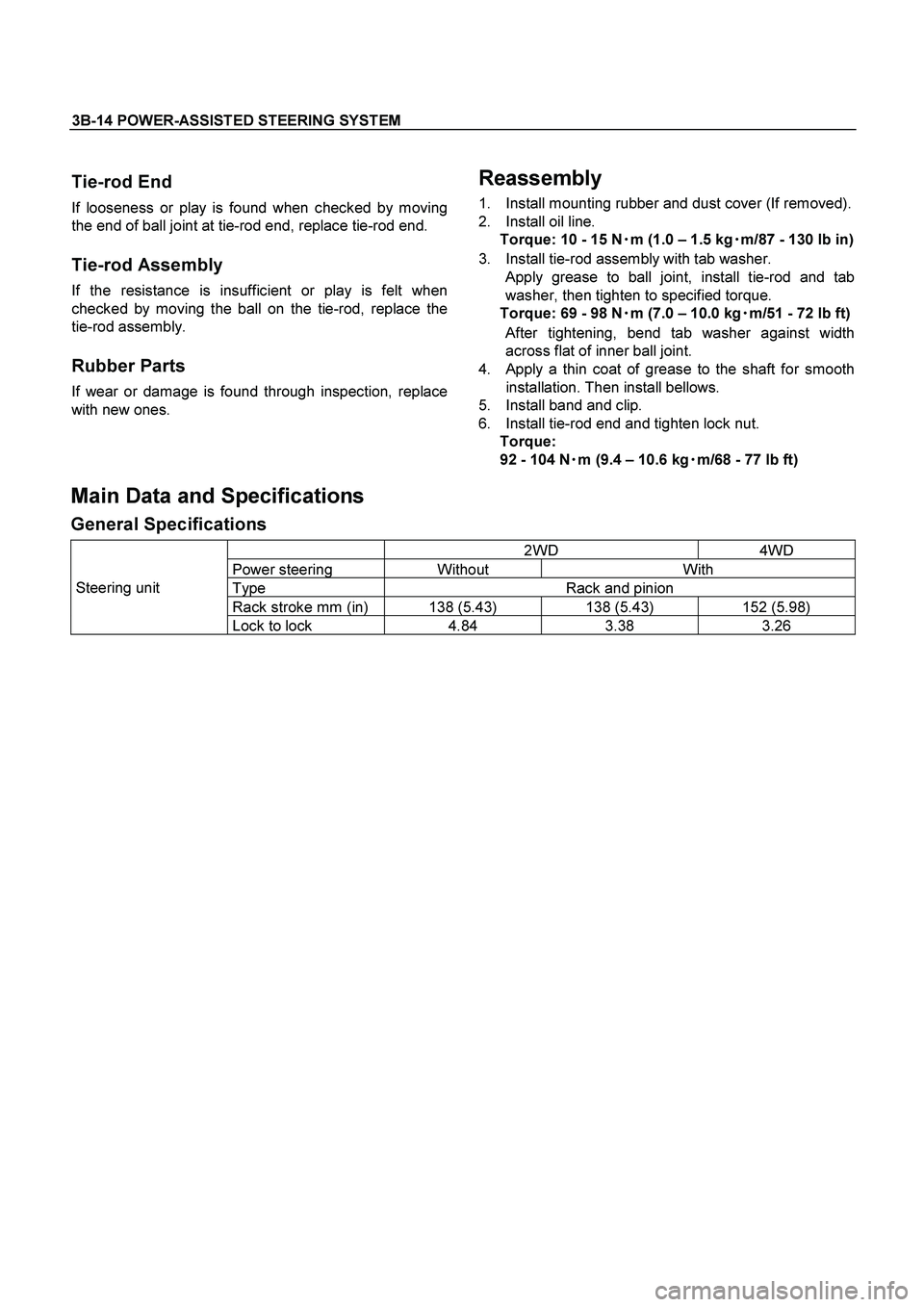
Main Data and Specifications
General Specifications
2WD 4WD
Power steering Without With
Type Rack and pinion
Rack stroke mm (in) 138 (5.43) 138 (5.43) 152 (5.98)
Steering unit
Lock to lock 4.84 3.38 3.26
Page 3591 of 4264
TRANSFER CASE 7D-3
General Description
RUW34DLF000701
The transfer case is used to provide a means of
providing power flow to the front axle. The transfer case
also provides a means of disconnecting the front axle,
providing better fuel economy and quieter operation
when the vehicle is driven on improved roads where
four wheel drive is not required. In addition, the transfer
case provides an additional gear reduction when placed
in low range, which is useful when difficult off-road
conditions are encountered.
Use the 4WD switch on the center cluster panel to
select the drive range. The 4WD indicator lamp will be
lit when 4WD is selected.
Page 3595 of 4264

TRANSFER CASE 7D-7
Removal
NOTE: Before removing transmission and transfer
assembly from vehicle, change the transfer mode to
2WD using the 4WD push button switch on dash panel.
1.
Disconnect battery ground cable.
2.
Raise and support vehicle with suitable stands. Drain
transfer case fluid.
3. Remove the center exhaust pipe(5). (6VE1 only)
4.
Remove rear propeller shaft (1) and front propelle
r
shaft (2)(3).
NOTE: Apply alignment marks on the flange at both
front and rear sides.
5.
Disconnect harness connectors and clip.
Connector: transfer switch, 2WD-4WD actuator,
speed sensor.
NOTE: Avoid turning the vehicle ignition switch to the
ON position when the 2WD-4WD connector is removed
(battery connected).
If the ignition switch must be turned to the ON position,
the controller must first be removed (memory must be
cleared because the CHECK 4WD INDICATOR will
light).
6.
Remove transfer case (4) from the vehicle.
Installation
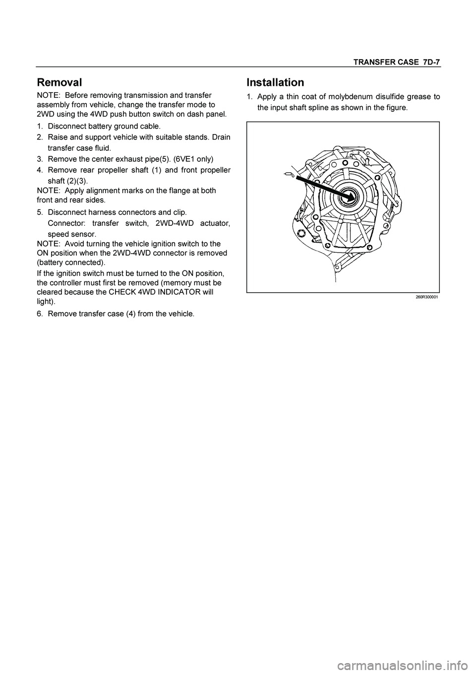
1.
Apply a thin coat of molybdenum disulfide grease to
the input shaft spline as shown in the figure.
260R300001
Page 3597 of 4264
TRANSFER CASE 7D-9
For A/T
261R300002
3.
Connect harness connectors and clip.
Connector: transfer switch, 2WD-4WD actuator,
speed sensor.
4. Install center exhaust pipe(5). (6VE1 only)
5.
Install rear propeller shaft (1) and front propelle
r
shaft (2)(3).
Torque: 63 N�
�� �m (6.4 kg�
�� �m/46 lb ft)
Page 3610 of 4264

7D-22 TRANSFER CASE
Block Ring and Insert Clearance
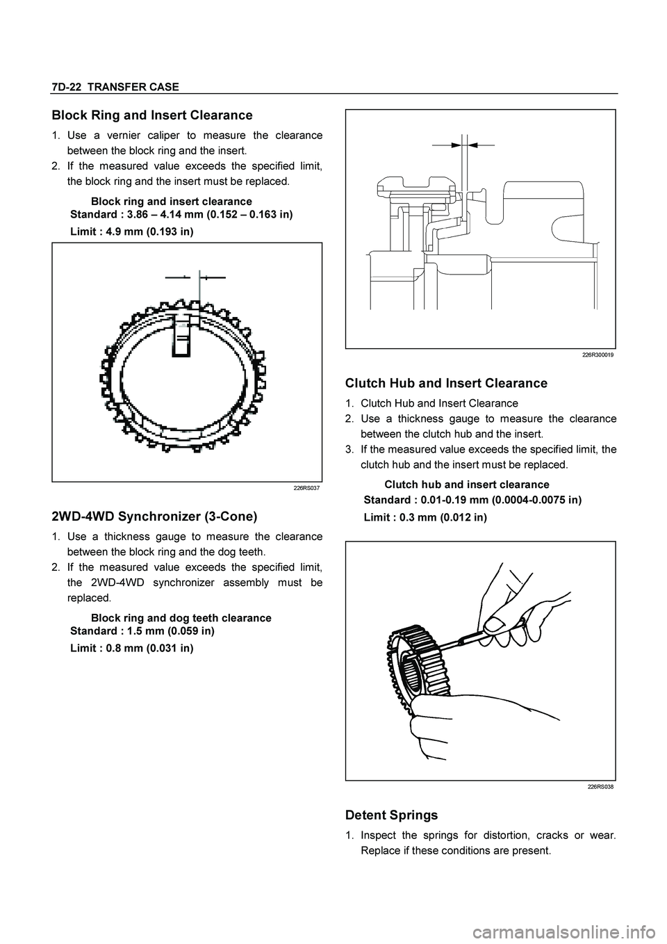
1.
Use a vernier caliper to measure the clearance
between the block ring and the insert.
2.
If the measured value exceeds the specified limit,
the block ring and the insert must be replaced.
Block ring and insert clearance
Standard : 3.86 – 4.14 mm (0.152 – 0.163 in)
Limit : 4.9 mm (0.193 in)
226RS037
2WD-4WD Synchronizer (3-Cone)
1.
Use a thickness gauge to measure the clearance
between the block ring and the dog teeth.
2.
If the measured value exceeds the specified limit,
the 2WD-4WD synchronizer assembly must be
replaced.
Block ring and dog teeth clearance
Standard : 1.5 mm (0.059 in)
Limit : 0.8 mm (0.031 in)
226R300019
Clutch Hub and Insert Clearance
1.
Clutch Hub and Insert Clearance
2.
Use a thickness gauge to measure the clearance
between the clutch hub and the insert.
3.
If the measured value exceeds the specified limit, the
clutch hub and the insert must be replaced.
Clutch hub and insert clearance
Standard : 0.01-0.19 mm (0.0004-0.0075 in)
Limit : 0.3 mm (0.012 in)
226RS038
Detent Springs
1.
Inspect the springs for distortion, cracks or wear.
Replace if these conditions are present.
Page 3629 of 4264
TRANSFER CONTROL SYSTEM 7D1-3
General Description
RTW47DLF000301
Transfer Position and Drive Mode
Three drive modes can be selected through operation of 4WD switch.
Transfer Position 4WD SWITCH Mode Drive mode
2H RWD Rear wheel drive
HIGH
4H 4WD (HIGH) High-speed mechanical
lock-up four wheel drive
LOW 4L 4WD (LOW) Low-speed mechanical
lock-up four wheel drive
NEUTRAL 2H & 4L (10 Sec) NEUTRAL Towed by other vehicle
Page 3631 of 4264
TRANSFER CONTROL SYSTEM 7D1-5
System Components
Parts Location
Speed sensor
Revolutions of the rear output shaft are decreased and taken
out by the speed/drive/driven gears installed in the transfer
case and the number of revolutions is detected with a speed
sensor.
About 4/3 pulses per revolution of the shaft is output.
4WD switch
The 4WD switch detects the movement of the shift rod driving
the 4�
2 - 4�
4 sleeve.
PUSH open is achieved with the PUSH open switch when the
shift rod is at the 4�2 position.
4�
�� �2 - 4�
�� �4 sleeve & Arm
The 4�2 - 4�4 sleeve moves directly in the 4�4 direction with
the 4�
2 - 4�
4 shift rod, but, when moving in 4�
2 direction, a