Page 1094 of 4264
8A-436 ELECTRICAL-BODY AND CHASSIS
No. Connector face No. Connector face
M-1
~
M-25 NOT USED
M-25
(6VE1)
2WD-4WD Switch
M-27
(6VE1)
H-L Neutral Switch
M-28
(6VE1)
Motor Actuator
Page 1096 of 4264
8A-438 ELECTRICAL-BODY AND CHASSIS
No. Connector face No. Connector face
R-1
Black
Front door switch-LH R-12
Pretensioner - RH
R-2
NOT USED R-13
Pretensioner - LH
R-3
Gray
Seat belt switch R-14
2-4WD control
R-4
Natural
Parking brake switch (Lever type) R-15
2-4WD control
R-5
NOT USED
R-6
Black
Front door switch-RH
R-7
~
R-8 NOT USED
R-9
Black
Rear speaker-LH
R-10
Black
Rear speaker-RH
R-11
Seat belt switch
Page 1416 of 4264
6E–44 4JA1/4JH1 ENGINE DRIVEABILITY AND EMISSIONS
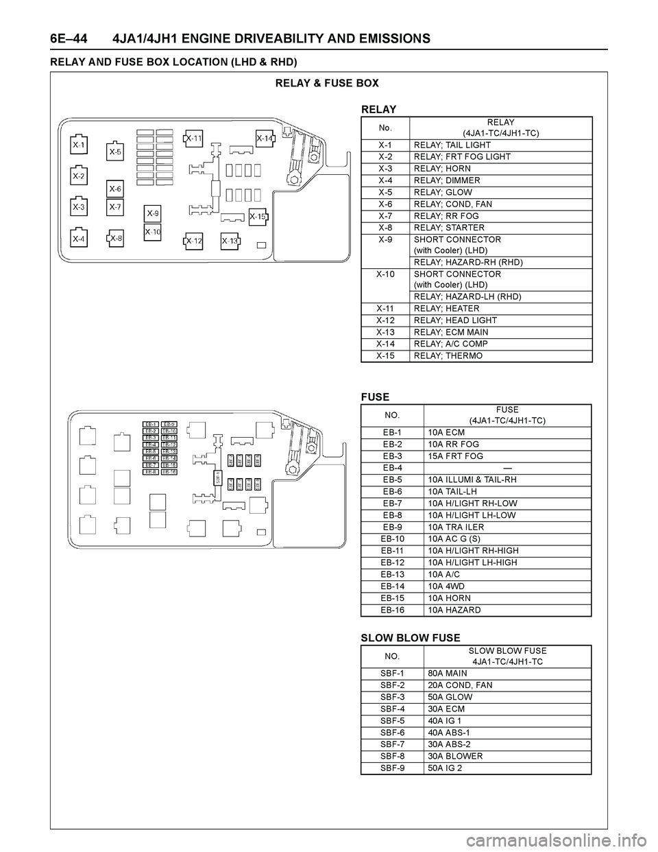
RELAY A ND FUSE BOX LOCATION (LHD & RHD)
RELAY & FUSE BOX
RELAY
No .RELAY
(4JA1-TC/4JH1-TC)
X -1 RELAY; TAIL LIGHT
X -2 RELAY; FRT F OG LI GHT
X -3 RELAY; HORN
X -4 RELAY; DIMMER
X -5 RELAY; GLOW
X -6 RELAY; COND, FAN
X -7 RELAY; RR FOG
X -8 RELAY; STARTER
X -9 SHORT CONNECTOR
(with Co oler) (LHD)
RELAY; HAZARD-RH (RHD)
X-10 SHORT CONNECTOR
(with Co oler) (LHD)
RELAY; HAZARD-LH (RHD)
X -11 RELAY; HEATER
X-12 RELAY; HEAD LIGHT
X-13 RELAY; ECM MAIN
X-14 RELAY; A/C COMP
X-15 RELAY; THERMO
FUSE
SLOW BLOW FUSE
NO.FUSE
(4JA1-TC/4JH1-TC)
EB-1 10A ECM
EB-2 10A RR FOG
EB-3 15A FRT FOG
EB-4 —
EB-5 10A ILLUMI & TAIL-RH
EB-6 10A TAIL-LH
EB-7 10A H/LIGHT RH-LOW
EB-8 10A H/LIGHT LH-LOW
EB-9 10A TRA ILER
EB-10 10A AC G (S)
EB-11 10A H/LIGHT RH-HIGH
EB-12 10A H/LIGHT LH-HIGH
EB-13 10A A/C
EB-14 10A 4WD
EB-15 10A HORN
EB-16 10A HAZARD
NO.SLOW BLOW FUSE
4JA1-TC/4JH1-TC
SBF-1 80A MAIN
SBF-2 20A COND, FAN
SBF-3 50A GLOW
SBF-4 30A ECM
SBF-5 40A IG 1
SBF-6 40A ABS-1
SBF-7 30A ABS-2
SBF-8 30A BLOWER
SBF-9 50A IG 2
Page 1439 of 4264
4JA1/4JH1 ENGINE DRIVEABILITY AND EMISSIONS 6E–67
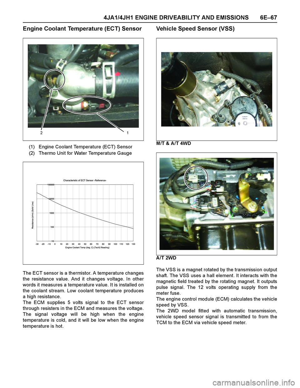
Engine Coolant Temperature (ECT) Sensor
The ECT sensor is a thermistor. A temperature changes
the resistance value. And it changes voltage. In other
words it measures a temperature value. It is installed on
the coolant stream. Low coolant temperature produces
a high resistance.
The ECM supplies 5 volts signal to the ECT sensor
through resisters in the ECM and measures the voltage.
The signal voltage will be high when the engine
temperature is cold, and it will be low when the engine
temperature is hot.
Vehicle Speed Sensor (VSS)
M/T & A /T 4WD
A/T 2WD
The VSS is a magnet rotated by the transmission output
shaft. The VSS uses a hall element. It interacts with the
magnetic field treated by the rotating magnet. It outputs
pulse signal. The 12 volts operating supply from the
meter fuse.
The engine control module (ECM) calculates the vehicle
speed by VSS.
The 2WD model fitted with automatic transmission,
vehicle speed sensor signal is transmitted to from the
TCM to the ECM via vehicle speed meter. (1) Engine Coolant Temperature (ECT) Sensor
(2) Thermo Unit for Water Temperature Gauge
12
Characteristic of ECT Sensor -Reference-
10 100 1000 10000 100000
-30 -20 -10 0 10 20 30 40 50 60 70 80 90 100 110 120 130
Engine Coolant Temp (deg. C) (Tech2 Reading)
Resistance (ohm) (Solid Line)
Page 2050 of 4264
6E-54 3.5L ENGINE DRIVEABILITY AND EMISSIONS
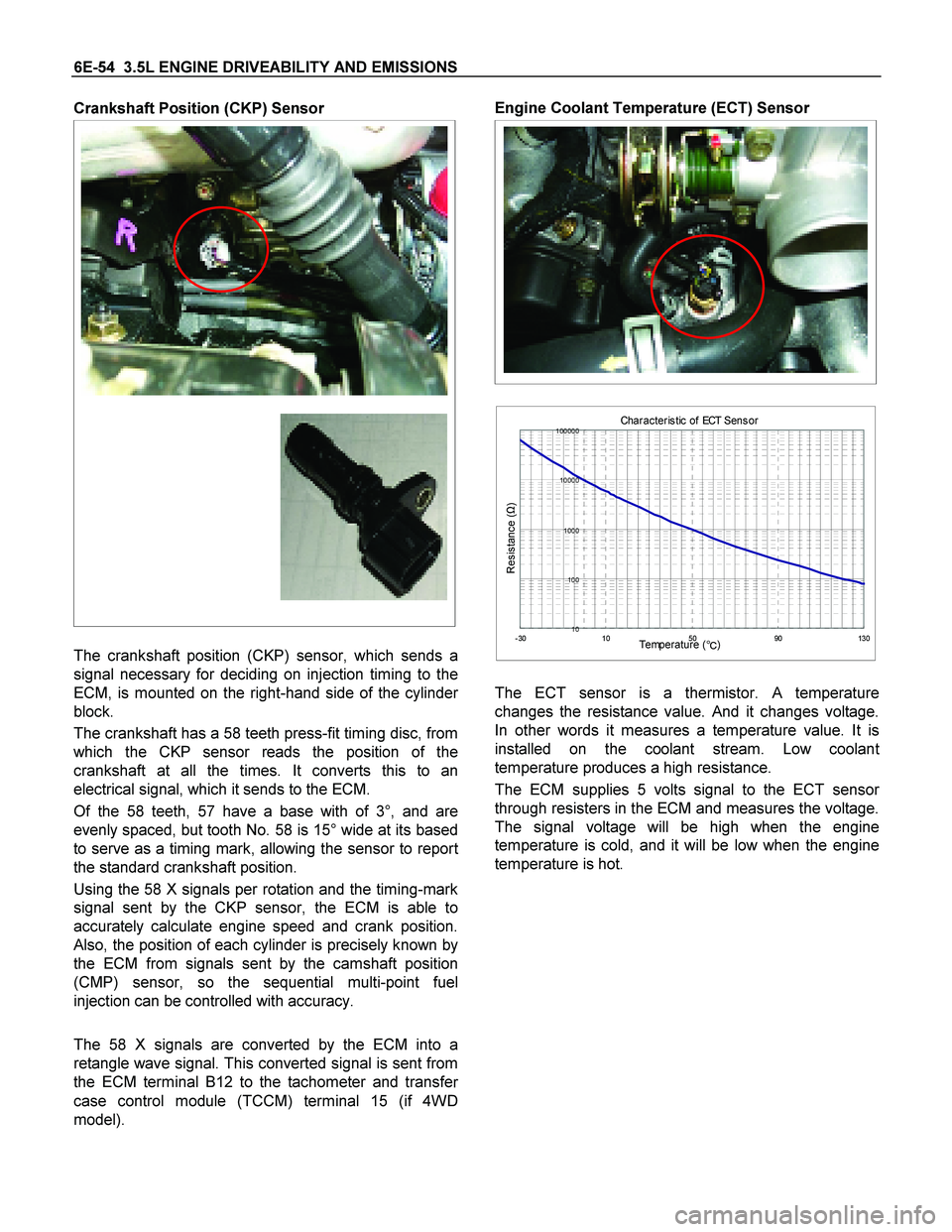
Crankshaft Position (CKP) Sensor
The crankshaft position (CKP) sensor, which sends a
signal necessary for deciding on injection timing to the
ECM, is mounted on the right-hand side of the cylinde
r
block.
The crankshaft has a 58 teeth press-fit timing disc, from
which the CKP sensor reads the position of the
crankshaft at all the times. It converts this to an
electrical signal, which it sends to the ECM.
Of the 58 teeth, 57 have a base with of 3°, and are
evenly spaced, but tooth No. 58 is 15° wide at its based
to serve as a timing mark, allowing the sensor to repor
t
the standard crankshaft position.
Using the 58 X signals per rotation and the timing-mark
signal sent by the CKP sensor, the ECM is able to
accurately calculate engine speed and crank position.
Also, the position of each cylinder is precisely known by
the ECM from signals sent by the camshaft position
(CMP) sensor, so the sequential multi-point fuel
injection can be controlled with accuracy.
The 58 X signals are converted by the ECM into a
retangle wave signal. This converted signal is sent from
the ECM terminal B12 to the tachometer and transfe
r
case control module (TCCM) terminal 15 (if 4WD
model).
Engine Coolant Temperature (ECT) Sensor
The ECT sensor is a thermistor. A temperature
changes the resistance value. And it changes voltage.
In other words it measures a temperature value. It is
installed on the coolant stream. Low coolan
t
temperature produces a high resistance.
The ECM supplies 5 volts signal to the ECT senso
r
through resisters in the ECM and measures the voltage.
The signal voltage will be high when the engine
temperature is cold, and it will be low when the engine
temperature is hot.
Characteris tic of ECT Sens or
10 100 1000 10000 100000-3010 50 90130Temperature (
�)
Resistance (Ω)
Page 2391 of 4264
ENGINE LUBRICATION (6VE1 3.5L) 6G-7
Oil Pan and Crankcase
Removal
1. Disconnect battery ground cable.
2. Drain engine oil.
3. Lift vehicle by supporting the frame.
4. Remove front wheels.
5. Remove oil level dipstick from level gauge tube.
6. Remove stone guard.
7. Remove radiator under fan shroud.
NOTE: For 4WD model, remove front axle housing
assembly from chassis (steps 8 to 10).
8. Remove suspension cross member fixing bolts, 2
pcs each per side and remove suspension cross
member.
9. Remove pitman arm and relay lever assembly,
using the 5–8840–2005–0 remover, remove pitman
arm from the steering unit and remove four fixing
bolts for relay lever assembly.
10. Remove axle housing assembly four fixing bolts
from housing isolator side and mounting bolts from
wheel side. At this time support the axle with a
garage jack and remove axle housing assembly.
11. Remove oil pan fixing bolts.
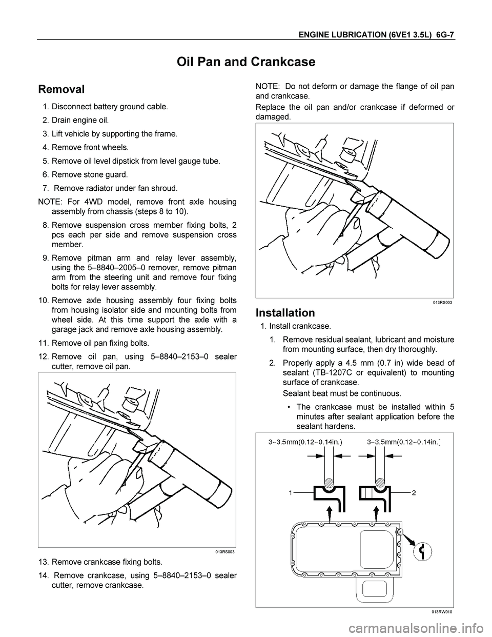
12. Remove oil pan, using 5–8840–2153–0 seale
r
cutter, remove oil pan.
013RS003
13. Remove crankcase fixing bolts.
14. Remove crankcase, using 5–8840–2153–0 seale
r
cutter, remove crankcase.
NOTE: Do not deform or damage the flange of oil pan
and crankcase.
Replace the oil pan and/or crankcase if deformed o
r
damaged.
013RS003
Installation
1. Install crankcase.
1. Remove residual sealant, lubricant and moisture
from mounting surface, then dry thoroughly.
2. Properly apply a 4.5 mm (0.7 in) wide bead o
f
sealant (TB-1207C or equivalent) to mounting
surface of crankcase.
Sealant beat must be continuous.
The crankcase must be installed within 5
minutes after sealant application before the
sealant hardens.
013RW010
Page 2392 of 4264
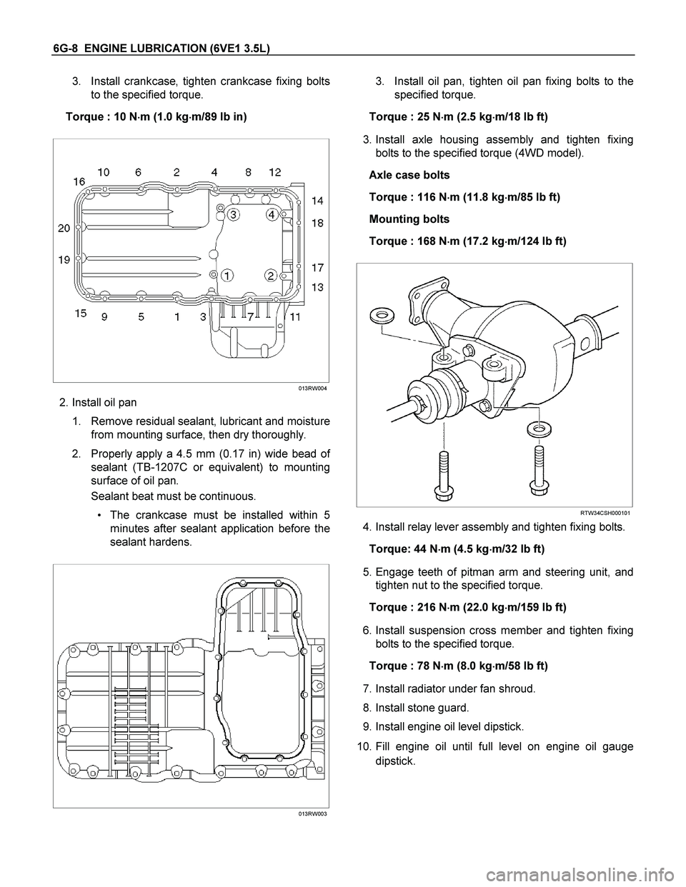
6G-8 ENGINE LUBRICATION (6VE1 3.5L)
3. Install crankcase, tighten crankcase fixing bolts
to the specified torque.
Torque : 10 N�
�� �m (1.0 kg�
�� �m/89 lb in)
013RW004
2. Install oil pan
1. Remove residual sealant, lubricant and moisture
from mounting surface, then dry thoroughly.
2. Properly apply a 4.5 mm (0.17 in) wide bead o
f
sealant (TB-1207C or equivalent) to mounting
surface of oil pan.
Sealant beat must be continuous.
The crankcase must be installed within 5
minutes after sealant application before the
sealant hardens.
013RW003
3. Install oil pan, tighten oil pan fixing bolts to the
specified torque.
Torque : 25 N�
�� �m (2.5 kg�
�� �m/18 lb ft)
3. Install axle housing assembly and tighten fixing
bolts to the specified torque (4WD model).
Axle case bolts
Torque : 116 N�
�� �m (11.8 kg�
�� �m/85 lb ft)
Mounting bolts
Torque : 168 N�
�� �m (17.2 kg�
�� �m/124 lb ft)
RTW34CSH000101
4. Install relay lever assembly and tighten fixing bolts.
Torque: 44 N�
�� �m (4.5 kg�
�� �m/32 lb ft)
5. Engage teeth of pitman arm and steering unit, and
tighten nut to the specified torque.
Torque : 216 N�
�� �m (22.0 kg�
�� �m/159 lb ft)
6. Install suspension cross member and tighten fixing
bolts to the specified torque.
Torque : 78 N�
�� �m (8.0 kg�
�� �m/58 lb ft)
7. Install radiator under fan shroud.
8. Install stone guard.
9. Install engine oil level dipstick.
10. Fill engine oil until full level on engine oil gauge
dipstick.
Page 2426 of 4264
6A-6 ENGINE MECHANICAL (C24SE)
ENGINE PICTORIAL
Front View
“4WD OIL PAN”