Page 2494 of 4264
6A-74 ENGINE MECHANICAL (C24SE)
RTW46JSH000101
Air Cleaner Filter
NOTE:
The air cleaner filter is not damaged with the edge of the air
cleaner housing.
Removal
(2.4L)
1. Remove air cleaner cover and air cleaner element.
2. Remove air intake nose.
3. Remove lower air cleaner.
4. Remove mud guard.
5. Remove front fender cover.
6. Remove outside air intake duct.
Inspection
Check the air cleaner filter for damage or dust clogging.
Replace if it is damaged, or clean if it is clogged.
130RW002
Cleaning Method
Tap the air cleaner filter gently so as not to damage the paper
filter, or clean the element by blowing with compressed air of
about 490 kPa (71 psi) from the clean side if it is extremely
dirty.
Installation
(2.4L)
1. Install outside air intake duct.
2. Install front fender cover.
3. Install mud guard.
4. Install lower air cleaner.
5. Install air intake hose.
6. Install air cleaner element and air cleaner cover.
Page 2498 of 4264
6A-78 ENGINE MECHANICAL (C24SE)
Adjustment Values/Checking Values
Valve clearance
Inlet Hydraulic valve lash adjustment
Outlet No adjustment necessary
Spark plugs - electrode gap 1.0 � 1.1mm
Compression The difference in compression
between the individual cylinders
in the engine must not exceed
100 kPa (1 bar).
Pressure loss The pressure loss of an engine
in perfect condition per cylinder
is not more than max. 25%
Cylinder Head
Cylinder Head Gasket
Thickness - installed mm 1.2
Valve seat width at cylinder head
inlet mm 1.0 to 1.5
outlet mm 1.7 to 2.2
Valve stem play inlet mm 0.018 to 0.052
outlet mm 0.038 to 0.072
Permissible valve stem to cone runout
inlet mm 0.03
outlet mm 0.33
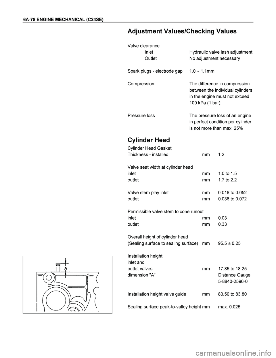
Overall height of cylinder head
(Sealing surface to sealing surface) mm 95.5 � 0.25
Installation height
inlet and
outlet valves mm 17.85 to 18.25
dimension "A" Distance Gauge
5-8840-2596-0
Installation height valve guide mm 83.50 to 83.80
Sealing surface peak-to-valley height mm max. 0.025
Page 2514 of 4264
6B-4 ENGINE COOLING
Antifreeze Solution
� Calculating mixing ratio
Mixing ratio
= Antifreeze solution (Lit/gal.)
Antifreeze solution (Lit/gal.) + Water (Lit/gal.)
NOTE: Antifreeze solution + Water = Total cooling system
capacity.
� Total Cooling System Capacity
5.7Lit
� Mixing ratio
Check the specific gravity of engine coolant in the cooling
system temperature ranges from 0�C to 50�C using a
suction type hydrometer, then determine the density of the
engine coolant by referring to the table.
NOTE: The LLC is 50% at all environment in order to prevent
the corrosion of cooling system parts.
Page 2516 of 4264

6B-6 ENGINE COOLING
Draining and Refilling Cooling
System
Before draining the cooling system, inspect the system and
perform any necessary service to ensure that it is clean, does
not leak and is in proper working order. The engine coolant
(EC) level should be between the "MIN" and "MAX" lines of
reserve tank when the engine is cold. If low, check for leakage
and add EC up to the "MAX" line. There should not be any
excessive deposit of rust or scales around the radiator cap or
radiator filler hole, and the EC should also be free from oil.
Replace the EC if excessively dirty.
1. Completely drain the cooling system by opening the drain
plug at the bottom of the radiator.
2. Remove the radiator cap.
WARNING: TO AVOID THE DANGER OF BEING BURNED,
DO NOT REMOVE THE CAP WHILE THE ENGINE AND
RADIATOR ARE STILL HOT. SCALDING FLUID AND
STEAM CAN BE BLOWN OUT UNDER PRESSURE.
3. Disconnect all hoses from the EC reserve tank.
Scrub and clean the inside of the reserve tank with soap
and water. Flush it well with clean water, then drain it. Install
the reserve tank and hoses.
4. Refill the cooling system with the EC using a solution that is
at least 50 percent antifreeze.
5. Fill the radiator to the base of the filler neck.
Fill the EC reserve tank to "MAX" line when the engine is
cold.
6. Block the drive wheels and firmly apply the parking brake.
Shift an automatic transmission to "P" (Park) or a manual
transmission to neutral.
7. Remove the radiator cap. Start the engine and warm it up a
t
2,500 - 3,000 rpm for about 30 minutes.
8. When the air comes out from the radiator filler neck and the
EC level has gone down, replenish with the EC. Repeat this
procedure until the EC level does not go down. Then stop
the engine and install the radiator cap. Let the engine cool
down.
9. After the engine has cooled, replenish with EC up to the
"MAX" line of the reserve tank.
10. Start the engine. With the engine running at 3,000 rpm,
make sure there is no running water sound from the heate
r
core (behind the center console).
11. If the running water sound is heard, repeat steps 8 to 10.
Page 2519 of 4264

ENGINE COOLING 6B-9
Thermostat
Removal
1. Disconnect battery ground cable.
2. Drain engine coolant from the radiator and engine.
3. Disconnect radiator hose from the inlet pipe.
4. Remove thermostat housing.
5. Remove thermostat from thermostat housing.
Inspection
Suspend the thermostat in a water-filled container using thin
wire. Place a thermometer next to the thermostat.
Do not directly heat the thermostat.
Gradually increase the water temperature. Stir the water so
that the entire water is same temperature.
Confirm the temperature when the valve first begins to open.
Valve opening temperature 92�
�� �C (197.6�
�� �F)
Confirm the temperature when the valve is fully opened.
Valve full open temperature 107�
�� �C(224.6�
�� �F)
Make necessary repair and parts replacement if extreme wear
or damage is found during inspection.
Installation
1. Before installing thermostat, coat sealing surface with
silicon grease.
2. Install O-ring.
3. Install thermostat housing and tighten bolts to the specified
torque.
Torque: 15 N�
�� �m (1.5 kgf�
�� �m)
4. Installation rubber hose.
5. Replenish engine coolant (EC).
6. Start engine and check for EC leakage.
Fan Clutch with Cooling Fan
Inspection and Repair
Make necessary correction or parts replacement if wear,
damage or any other abnormal condition are found through
inspection.
Visually inspect for damage, leak (silicon grease) or other
abnormal conditions.
1. Inspection (on-vehicle)
1) Turn the fan clutch by hand when in a low temperature
condition before starting the engine, and confirm that it
can be turned readily.
2) Start the engine to warm it up until the temperature at the
fan clutch portion gets to around 80�C. Then stop the
engine and confirm that the fan clutch can be turned with
considerable effort (clutch torque) when turned by hand.
Page 2522 of 4264

6B-12 ENGINE COOLING
Inspection
Radiator Cap
Measure the valve opening pressure of the pressurizing valve
with a radiator filler cap tester.
Replace the cap if the valve opening pressure is outside the
standard range.
Valve opening pressure kPa (psi) 88.3 – 103.0
(13.5 – 15.7)
Cap tester: 5-8840-0277-0
Adapter: 5-8840-2603-0
Check the condition of the vacuum valve in the center of the
valve seat side of the cap. If considerable rust or dirt is found,
or if the valve seat cannot be moved by hand, clean or replace
the cap.
Valve opening vacuum kPa (psi) 1.9 - 4.9
(0.28 - 0.71)
Radiator Core
1. A bent fin may result in reduced ventilation and overheating
may occur. All bent fins must be straightened. Pay close
attention to the base of the fin when it is being straightened.
2. Remove all dust, bugs and other foreign material.
Flushing the Radiator
Thoroughly wash the inside of the radiator and the engine
coolant passages with cold water and mild detergent. Remove
all sign of scale and rust.
Cooling System Leakage Check
Use a radiator cap tester to force air into the radiator through
the filler neck at the specified pressure of 196 kPa (28.5 psi)
with a cap tester:
� Leakage from the radiator
� Leakage from the coolant pump
� Leakage from the water hoses
� Check the rubber hoses for swelling.
Cap tester: 5-8840-0277-0
Adapter: 5-8840-2603-0
Page 2527 of 4264
 6C-3
When working on the fuel system, there are several things to
keep in mind:
�
Any time the fuel system is being worked on, disconnect the
negative battery cable excep")
ENGINE FUEL (C24SE) 6C-3
When working on the fuel system, there are several things to
keep in mind:
�
Any time the fuel system is being worked on, disconnect the
negative battery cable except for those tests where battery
voltage is required.
�
Always keep a dry chemical (Class B) fire extinguisher near
the work area.
� Replace all pipes with the same pipe and fittings that were
removed.
� Clean and inspect "O" rings. Replace if required.
�
Always relieve the line pressure before servicing any fuel
system components.
� Do not attempt repairs on the fuel system until you have
read the instructions and checked the pictures relating to
that repair.
� Adhere to all Notices and Cautions.
All gasoline engines are designed to use only unleaded
gasoline. Unleaded gasoline must be used for proper emission
control system operation.
Its use will also minimize spark plug fouling and extend engine
oil life. Using leaded gasoline can damage the emission control
system and could result in loss of emission warranty coverage.
All cars are equipped with an Evaporative Emission Control
System. The purpose of the system is to minimize the escape
of fuel vapors to the atmosphere.
Service Precaution
CAUTION:
Always use the correct fastener in the proper location.
When you replace a fastener, use ONLY the exact part
number for that application. ISUZU will call out those
fasteners that require a replacement after removal. ISUZU
will also call out the fasteners that require thread lockers
or thread sealant. UNLESS OTHERWISE SPECIFIED, do
not use supplemental coatings (Paints, greases, or othe
r
corrosion inhibitors) on threaded fasteners or fastene
r
joint interfaces. Generally, such coatings adversely affect
the fastener torque and the joint clamping force, and may
damage the fastener. When you install fasteners, use the
correct tightening sequence and specifications. Following
these instructions can help you avoid damage to parts
and systems.
Page 2529 of 4264
ENGINE FUEL (C24SE) 6C-5
Fuel Filter
Fuel Filter and Associated Parts
Removal
CAUTION: When repair to the fuel system has been
completed, start engine and check the fuel system fo
r
loose connections or leakage. For the fuel system
diagnosis, see Section "Driveability and Emissions".
(2.4L)
1. Disconnect battery ground cable.
2. Disconnect the quick connector from the fuel filter.
3. Pull off fuel filter from the holder to side member side.
4. Remove the fuel filter.

RTW46JSH000101
Air Cleaner Filter
NOTE:
The air cleaner filter is not damaged with the edge of the air
cleaner housing.
Removal
(2.4L)")
 6C-5
Fuel Filter
Fuel Filter and Associated Parts
Removal
CAUTION: When repair to the fuel system has been
completed, start engine and check the fuel system fo")