Page 834 of 4264
8A-176 ELECTRICAL-BODY AND CHASSIS
This illustration is based on RHD model
TURN SIGNAL SWITCH
Removal
1. Disconnect the battery ground cable.
2. Remove the steering wheel
1.
Refer to the “STEERING” Section of this Manual.
3. Remove the instruments panel lower cover
2.
4. Remove the steering column cover
3.
This illustration is based on RHD model
5. Disconnect the connector.
6. Remove the turn signal switch from the steering shaft.
Installation
Follow the removal procedure in the reverse order to install the
turn signal switch (lever).
Pay close attention to the important points mentioned in the
following paragraphs.
Connector
Be absolutely sure that the turn signal switch connector is
securely connected.
This will prevent a poor contact and at an open circuit.
Page 837 of 4264
ELECTRICAL-BODY AND CHASSIS 8A-179
HORN SWITCH
Removal
1. Disconnect the battery ground cable.
2. Disable the SRS (Refer to “Disabling the SRS”in this
section).
3. Check the both side hole of the steering cover.
4. Check the position of the pins in a hole. Push the pin in the
direction of an arrow.
5. Push the four pins at �5�6 mm bar.
6. Cancel the lock four pins.
7. Disconnect the SRS air bag connector and horn lead
connector located behind the air bag assembly and remove
the air bag assembly.
Installation
1. Connect the SRS bag connector and horn lead connector.
2.
Align the each snap stud of driver air bag to the hole of
steering wheel.
Page 1104 of 4264

8B-6 CRUISE CONTROL SYSTEM
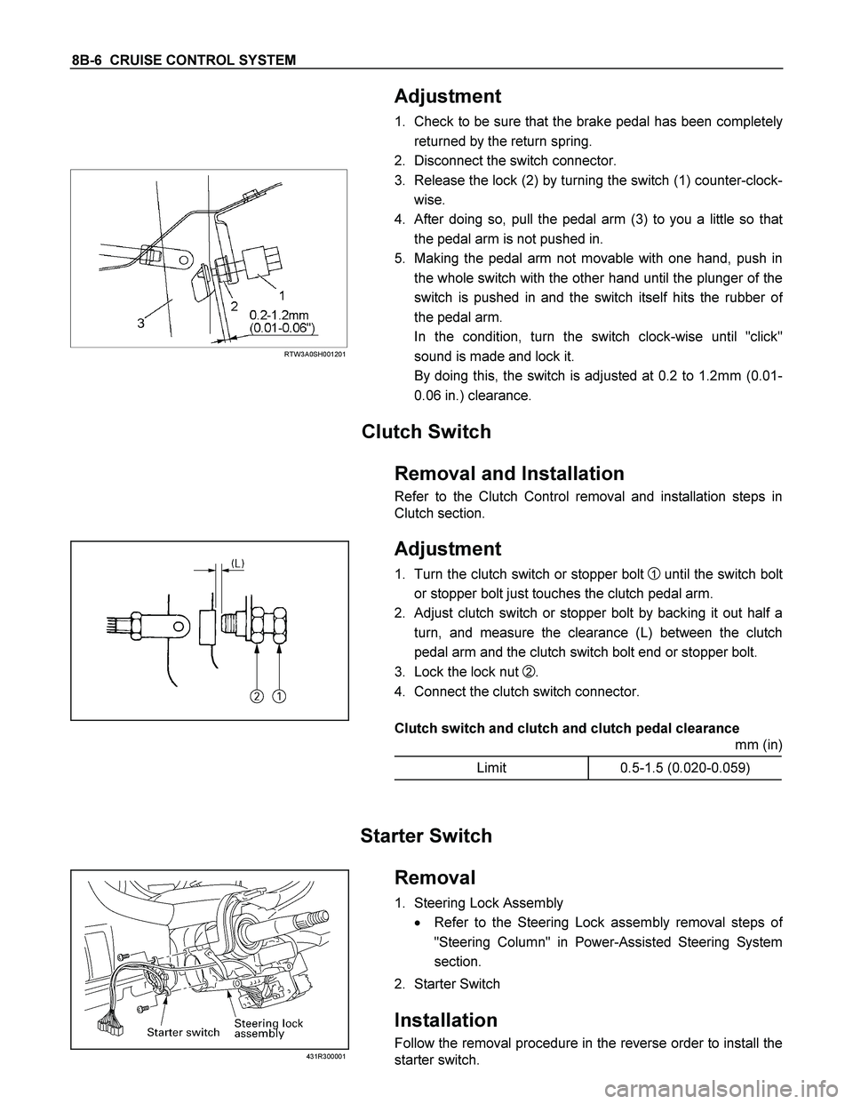
Adjustment
1. Check to be sure that the brake pedal has been completely
returned by the return spring.
2. Disconnect the switch connector.
RTW3A0SH001201
3. Release the lock (2) by turning the switch (1) counter-clock-
wise.
4. After doing so, pull the pedal arm (3) to you a little so tha
t
the pedal arm is not pushed in.
5. Making the pedal arm not movable with one hand, push in
the whole switch with the other hand until the plunger of the
switch is pushed in and the switch itself hits the rubber o
f
the pedal arm.
In the condition, turn the switch clock-wise until "click"
sound is made and lock it.
By doing this, the switch is adjusted at 0.2 to 1.2mm (0.01-
0.06 in.) clearance.
Clutch Switch
Removal and Installation
Refer to the Clutch Control removal and installation steps in
Clutch section.
Adjustment
1. Turn the clutch switch or stopper bolt 1 until the switch bolt
or stopper bolt just touches the clutch pedal arm.
2. Adjust clutch switch or stopper bolt by backing it out half a
turn, and measure the clearance (L) between the clutch
pedal arm and the clutch switch bolt end or stopper bolt.
3. Lock the lock nut
2.
4. Connect the clutch switch connector.
Clutch switch and clutch and clutch pedal clearance
mm (in)
Limit 0.5-1.5 (0.020-0.059)
Starter Switch
431R300001
Removal
1. Steering Lock Assembly
� Refer to the Steering Lock assembly removal steps o
f
"Steering Column" in Power-Assisted Steering System
section.
2. Starter Switch
Installation
Follow the removal procedure in the reverse order to install the
starter switch.
Page 1179 of 4264

ENGINE MECHANICAL 6A – 39
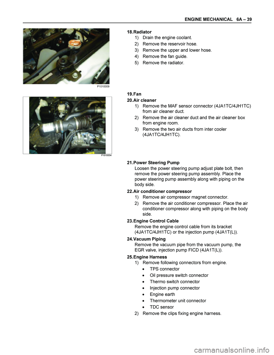
18. Radiator
1) Drain the engine coolant.
2) Remove the reservoir hose.
3) Remove the upper and lower hose.
4) Remove the fan guide.
5) Remove the radiator.
19. Fan
P1010034
20. Air cleaner
1) Remove the MAF sensor connector (4JA1TC/4JH1TC) from air cleaner duct.
2) Remove the air cleaner duct and the air cleaner box from engine room.
3) Remove the two air ducts from inter cooler (4JA1TC/4JH1TC).
21. Power Steering Pump Loosen the power steering pump adjust plate bolt, then
remove the power steering pump assembly. Place the
power steering pump assembly along with piping on the
body side.
22. Air conditioner compressor 1) Remove air compressor magnet connector.
2) Remove the air conditioner compressor. Place the air conditioner compressor along with piping on the body
side.
23. Engine Control Cable Remove the engine control cable from its bracket
(4JA1TC/4JH1TC) or the injection pump (4JA1T(L)).
24. Vacuum Piping Remove the vacuum pipe from the vacuum pump, the
EGR valve, injection pump FICD (4JA1T(L)).
25. Engine Harness 1) Remove following connectors from engine.
� TPS connector
� Oil pressure switch connector
� Thermo switch connector
� Injection pump connector
� Engine earth
� Thermometer unit connector
� TDC sensor
2) Remove the clips fixing engine harness.
P1010009
Page 1183 of 4264
ENGINE MECHANICAL 6A – 43
ENGINE OVERHAUL
REMOVAL
EXTERNAL PARTS
RTW36AMF000401
Removal Steps
1. Clutch Assembly or Flex Plate
2. Intake Pipe and Throttle Body
3-1. EGR Pipe
3-2. EGR cooler (EURO III model only)
4. EGR Valve
5. Oil Level Gauge
6. Fuel Filter Assembly (Except EURO III)
7. Fuel Filter Bracket (Except EURO III)
8. Fuel Injection Pipe with Clip
9. Power Steering Oil Pump Bracket
10. Intake Manifold
11. Engine Mounting Bracket and Foot
12. Injection Pump Cover
13. Injection Pump
14. Starter Motor
15. Oil Pressure Warning Switch
16. Fuel Leak Off Pipe
17. Oil Cooler Water Pipe
18. Cooling Fan Pulley
19. Heat Protector
20. Catalytic Converter
21. Turbocharger
22. Compressor Bracket
23. Vacuum Pump Oil Return Hose
24. Generator and Adjusting Plate
25. Water Inlet Pipe
26. Generator Bracket
27. Oil Cooler with Oil Filter
28. Exhaust Manifold
Page 1185 of 4264

ENGINE MECHANICAL 6A – 45
4JA1�L
RTW46ASH001001
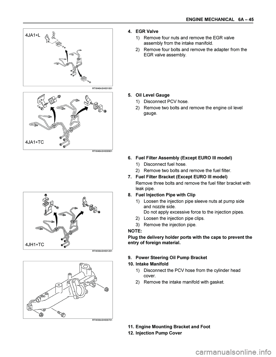
4. EGR Valve
1) Remove four nuts and remove the EGR valve
assembly from the intake manifold.
2) Remove four bolts and remove the adapter from the
EGR valve assembly.
4JA1�TC RTW46ASH000901
5. Oil Level Gauge
1) Disconnect PCV hose.
2) Remove two bolts and remove the engine oil level
gauge.
6. Fuel Filter Assembly (Except EURO III model)
1) Disconnect fuel hose.
2) Remove two bolts and remove the fuel filter.
7. Fuel Filter Bracket (Except EURO III model)
Remove three bolts and remove the fuel filter bracket with
leak pipe.
4JH1�TC RTW36ASH001201
8. Fuel Injection Pipe with Clip
1) Loosen the injection pipe sleeve nuts at pump side
and nozzle side.
Do not apply excessive force to the injection pipes.
2) Loosen the injection pipe clips.
3) Remove the injection pipe.
NOTE:
Plug the delivery holder ports with the caps to prevent the
entry of foreign material.
9. Power Steering Oil Pump Bracket
RTW36ASH000701
10. Intake Manifold
1) Disconnect the PCV hose from the cylinder head
cover.
2) Remove the intake manifold with gasket.
11. Engine Mounting Bracket and Foot
12. Injection Pump Cover
Page 1258 of 4264
6A – 118 ENGINE MECHANICAL
INSTALLATION
EXTERNAL PARTS
RTW36AMF000701
Installation Steps
1.
Exhaust Manifold 18. Engine Mounting Bracket and
2.
Oil Cooler with Oil Filter Foot
3. Generator Bracket 19. Intake Manifold
4. Water Inlet Pipe 20. Power Steering Oil Pump
5.
Generator and Adjusting Plate Bracket
6.
Vacuum Pump Oil Return Hose 21. Fuel Injection Pipe with Clip
7.
Compressor Bracket 22. Fuel Filter Bracket (Except
EURO III)
8. Turbocharger 23. Fuel Filter Assembly (Except
EURO III)
9. Catalytic Converter 24. Oil Level Gauge
10. Heat Protector 25. EGR Valve
11. Cooling Fan Pulley 26-1. EGR Pipe
12. Oil Cooler Water Pipe 26-2. EGR Cooler (EURO III model
only)
13. Fuel Leak Off Pipe 27. Intake Pipe and Throttle Body
(4JA1TC/4JH1TC only)
14. Oil Pressure Warning Switch 28. Clutch Assembly or Flex Plate
15. Starter Motor
16. Injection Pump
17. Injection Pump Cover
Page 1264 of 4264

6A – 124 ENGINE MECHANICAL
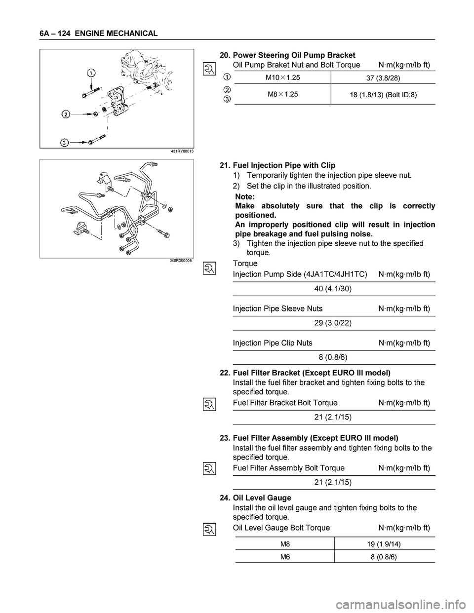
20. Power Steering Oil Pump Bracket
Oil Pump Braket Nut and Bolt Torque N·m(kg·m/Ib ft)
1M10�1.25
37 (3.8/28)
2
3M8�1.25
18 (1.8/13) (Bolt ID:8)
040R300005
21. Fuel Injection Pipe with Clip
1) Temporarily tighten the injection pipe sleeve nut.
2) Set the clip in the illustrated position.
Note:
Make absolutely sure that the clip is correctly
positioned.
An improperly positioned clip will result in injection
pipe breakage and fuel pulsing noise.
3) Tighten the injection pipe sleeve nut to the specified
torque.
Torque
Injection Pump Side (4JA1TC/4JH1TC) N·m(kg·m/Ib ft)
40 (4.1/30)
Injection Pipe Sleeve Nuts N·m(kg·m/Ib ft)
29 (3.0/22)
Injection Pipe Clip Nuts N·m(kg·m/Ib ft)
8 (0.8/6)
22. Fuel Filter Bracket (Except EURO III model)
Install the fuel filter bracket and tighten fixing bolts to the
specified torque.
Fuel Filter Bracket Bolt Torque N·m(kg·m/Ib ft)
21 (2.1/15)
23. Fuel Filter Assembly (Except EURO III model)
Install the fuel filter assembly and tighten fixing bolts to the
specified torque.
Fuel Filter Assembly Bolt Torque N·m(kg·m/Ib ft)
21 (2.1/15)
24. Oil Level Gauge
Install the oil level gauge and tighten fixing bolts to the
specified torque.
Oil Level Gauge Bolt Torque N·m(kg·m/Ib ft)
M8 19 (1.9/14)
M6 8 (0.8/6)
431RY00013