Page 3621 of 4264
TRANSFER CASE 7D-33
Main Data and Specifications
General Specifications
Type Synchronized type gears shifting between the 2 and 4 wheel drive mode.
Planetary type gears shifting between “low" and “high".
Control method Remote control with the button switch on the instrument panel for gears
shifting among “2H" , “4H" and “4L".
Gear ratio High; 1.000
Low; 2.482
Oil capacity 1.3 lit. (1.37 U.S. quart)
Type of lubricant BESCO GEAR OIL TRANSAXLE (5W-30)
Refer to chart in Section 0
Torque Specifications
N�m (kg�m/lb ft)
RTW47DLF000201
Page 3630 of 4264

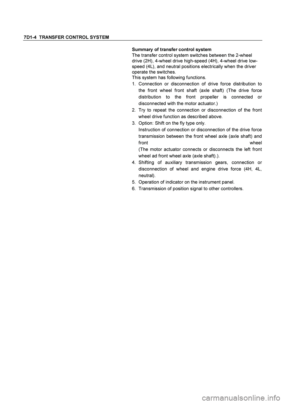
7D1-4 TRANSFER CONTROL SYSTEM
Summary of transfer control system
The transfer control system switches between the 2-wheel
drive (2H), 4-wheel drive high-speed (4H), 4-wheel drive low-
speed (4L), and neutral positions electrically when the driver
operate the switches.
This system has following functions.
1. Connection or disconnection of drive force distribution to
the front wheel front shaft (axle shaft) (The drive force
distribution to the front propeller is connected o
r
disconnected with the motor actuator.)
2. Try to repeat the connection or disconnection of the front
wheel drive function as described above.
3. Option: Shift on the fly type only.
Instruction of connection or disconnection of the drive force
transmission between the front wheel axle (axle shaft) and
front wheel
(The motor actuator connects or disconnects the left front
wheel ad front wheel axle (axle shaft).).
4. Shifting of auxiliary transmission gears, connection o
r
disconnection of wheel and engine drive force (4H, 4L,
neutral).
5. Operation of indicator on the instrument panel.
6. Transmission of position signal to other controllers.
Page 3695 of 4264

TRANSMISSION CONTROL SYSTEM (AW30 –40LE) (V6 3.5L) 7A2-15
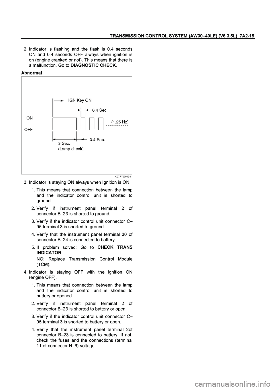
2. Indicator is flashing and the flash is 0.4 seconds
ON and 0.4 seconds OFF always when ignition is
on (engine cranked or not). This means that there is
a malfunction. Go to DIAGNOSTIC CHECK
.
Abnormal
C07RY00042-1
3. Indicator is staying ON always when Ignition is ON.
1. This means that connection between the lamp
and the indicator control unit is shorted to
ground.
2. Verify if instrument panel terminal 2 o
f
connector B –23 is shorted to ground.
3. Verify if the indicator control unit connector C –
95 terminal 3 is shorted to ground.
4.
Verify that the instrument panel terminal 30 of
connector B –24 is connected to battery.
5. If problem solved: Go to CHECK TRANS
INDICATOR .
NO: Replace Transmission Control Module
(TCM).
4. Indicator is staying OFF with the ignition ON
(engine OFF).
1. This means that connection between the lamp
and the indicator control unit is shorted to
battery or opened.
2.
Verify if instrument panel terminal 2 of
connector B –23 is shorted to battery or open.
3. Verify if the indicator control unit connector C –
95 terminal 3 is shorted to battery or open.
4.
Verify that the instrument panel terminal 2of
connector B –23 is connected to battery. If not,
check the fuses and the connections (terminal
11 of connector H –6) voltage.
Page 3711 of 4264
TRANSMISSION CONTROL SYSTEM (AW30 –40LE) (V6 3.5L) 7A2-31
16 – Terminal Data Link Connector (DLC)
OBD standardizes Data Link Connector (DLC)
configurations. The DLC, formerly referred to as the
ALDL, will be a 16 –terminal connector found on the
lower right side of the driver's side instrument panel. All
manufacturers must conform to this 16 –terminal
standard.
060R300015
810RT022
PIN 1 – uart
PIN 2 – J1850 Bus + L line on 2–wire systems, or single wire (ECM)
PIN 3 – (Not used)
PIN 4 – Chassis ground pin
PIN 5 – Chassis ground pin
PIN 6 – ECM diagnostic enable
PIN 7 – KW2000
PIN 8 – (Not used)
PIN 9 – Primary UART
PIN 10 – (Not used)
PIN 11 – TCM diagnostic enable
PIN 12 – ABS diagnostic or CCM diagnostic enable
PIN 13 – SIR diagnostic enable
PIN 14 – (Not used)
PIN 15 – (Not used)
PIN 16 – Battery power from vehicle unswitched (4 AMP MAX.)
Page 3790 of 4264
7A3-34 ON-VEHICLE SERVICE (AW30 –40LE)
Transmission Control Module (TCM)
RTW37ALF001801
Removal
Preparation:
Disconnect negative ( –) battery cable.
1. Disconnect the TCM harness connectors.
2. Remove fixing nuts (2 pieces) and TCM with bracket from the car.
NOTE: The TCM is fitted under instrument panel of the
driver's compartment by means of two stud bolts.
3. Remove fixing nuts (2 pieces) and remove TCM
from bracket.
Installation
To install, follow the removal steps in reverse order.
Page 3952 of 4264
7A1-6 CONSTRUCTION AND FUNCTION
ELECTRONIC CONTROL COMPONENTS LOCATION
4WD Only 4WD Only
Instrument panel (Meter)
Speed meter (2WD Only)
Shift position indicator lamp
POWER DRIVE, 3rd START
indicator lamp
A/T OIL TEMP indicator lamp
CHECK TRANS indicator lam
p
Brake pedal
Brake Switch
Select lever
Power Drive
, 3rd Start select switch
Transmission Control Module (TCM)
Electrical source
Ignition
Battery voltage
Speed sensor
Turbine sensor
Inhibitor switch
ATF thermo sensor
High clutch oil pressure switch
2-4 brake oil pressure switch
Low & Reverse brake oil pressure
switch
Line pressure solenoid
Low clutch solenoid
High clutch solenoid
2-4 brake solenoid
Low & Reverse brake solenoid
Lock-up solenoid
Transmission
Transfer Control Module
Transfer
4L mode switch
Engine
Engine speed sensor
Throttle Position Sensor
Engine Control Module (ECM)
Data link connector
Page 4083 of 4264

DIAGNOSIS (JR405E) 7A2-91
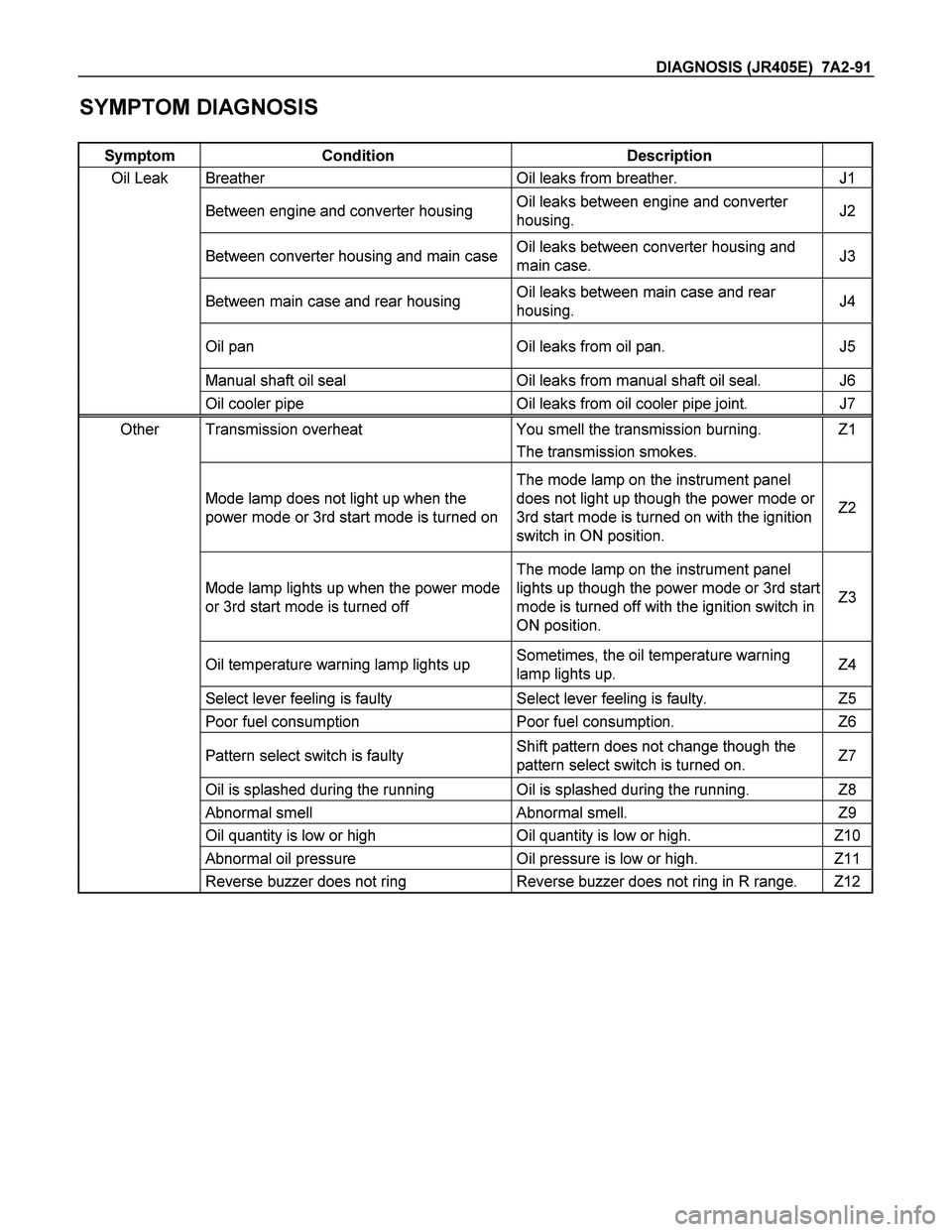
SYMPTOM DIAGNOSIS
Symptom Condition Description
Oil Leak Breather Oil leaks from breather. J1
Between engine and converter housing Oil leaks between engine and converter
housing. J2
Between converter housing and main caseOil leaks between converter housing and
main case. J3
Between main case and rear housing Oil leaks between main case and rear
housing. J4
Oil pan Oil leaks from oil pan. J5
Manual shaft oil seal Oil leaks from manual shaft oil seal. J6
Oil cooler pipe Oil leaks from oil cooler pipe joint. J7
Other Transmission overheat You smell the transmission burning. Z1
� The transmission smokes.
Mode lamp does not light up when the
power mode or 3rd start mode is turned on
The mode lamp on the instrument panel
does not light up though the power mode or
3rd start mode is turned on with the ignition
switch in ON position.
Z2
Mode lamp lights up when the power mode
or 3rd start mode is turned off
The mode lamp on the instrument panel
lights up though the power mode or 3rd start
mode is turned off with the ignition switch in
ON position.
Z3
Oil temperature warning lamp lights up Sometimes, the oil temperature warning
lamp lights up. Z4
Select lever feeling is faulty Select lever feeling is faulty. Z5
Poor fuel consumption Poor fuel consumption. Z6
Pattern select switch is faulty Shift pattern does not change though the
pattern select switch is turned on. Z7
Oil is splashed during the running Oil is splashed during the running. Z8
Abnormal smell Abnormal smell. Z9
Oil quantity is low or high Oil quantity is low or high. Z10
Abnormal oil pressure Oil pressure is low or high. Z11
Reverse buzzer does not ring Reverse buzzer does not ring in R range. Z12
Page 4129 of 4264

DIAGNOSIS (JR405E) 7A2-137
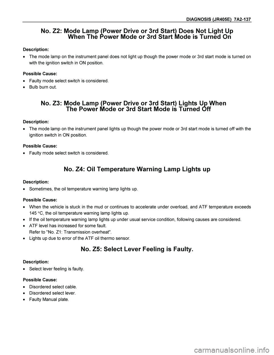
No. Z2: Mode Lamp (Power Drive or 3rd Start) Does Not Light Up
When The Power Mode or 3rd Start Mode is Turned On
Description:
� The mode lamp on the instrument panel does not light up though the power mode or 3rd start mode is turned on
with the ignition switch in ON position.
Possible Cause:
� Faulty mode select switch is considered.
� Bulb burn out.
No. Z3: Mode Lamp (Power Drive or 3rd Start) Lights Up When
The Power Mode or 3rd Start Mode is Turned Off
Description:
� The mode lamp on the instrument panel lights up though the power mode or 3rd start mode is turned off with the
ignition switch in ON position.
Possible Cause:
� Faulty mode select switch is considered.
No. Z4: Oil Temperature Warning Lamp Lights up
Description:
� Sometimes, the oil temperature warning lamp lights up.
Possible Cause:
� When the vehicle is stuck in the mud or continues to accelerate under overload, and ATF temperature exceeds
145 �C, the oil temperature warning lamp lights up.
� If the oil temperature warning lamp lights up under usual service condition, following causes are considered.
� ATF level has increased for some fault.
Refer to "No. Z1: Transmission overheat".
� Lights up due to error of the ATF oil thermo sensor.
No. Z5: Select Lever Feeling is Faulty.
Description:
� Select lever feeling is faulty.
Possible Cause:
� Disordered select cable.
� Disordered select lever.
� Faulty Manual plate.