Page 3080 of 4264
1-70 HEATER AND AIR CONDITIONING
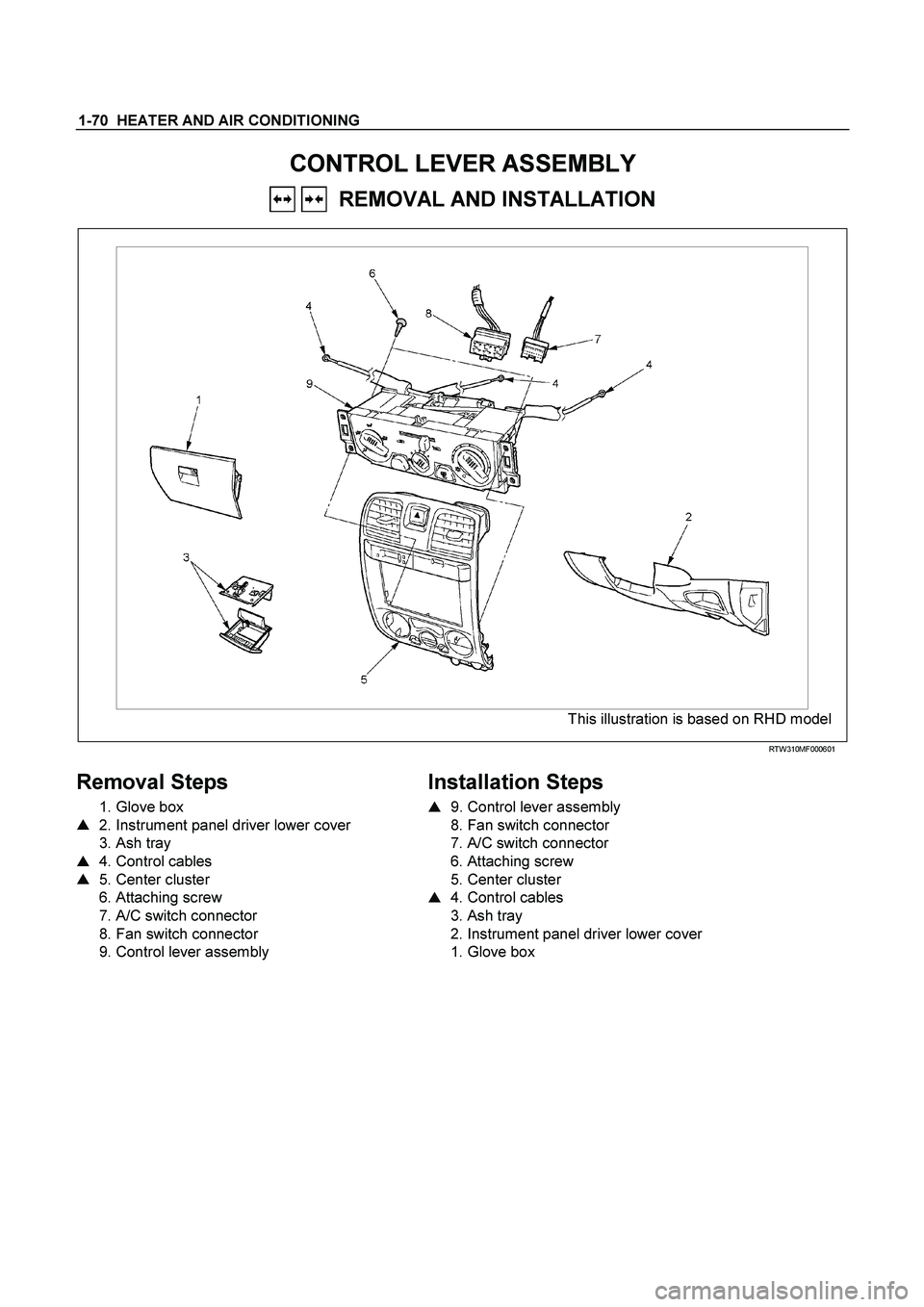
CONTROL LEVER ASSEMBLY
REMOVAL AND INSTALLATION
This illustration is based on RHD model
RTW310MF000601
Removal Steps
1. Glove box
� 2. Instrument panel driver lower cover
3. Ash tray
� 4. Control cables
� 5. Center cluster
6. Attaching screw
7. A/C switch connector
8. Fan switch connector
9. Control lever assembly
Installation Steps
�
9. Control lever assembly
8. Fan switch connector
7. A/C switch connector
6. Attaching screw
5. Center cluster
� 4. Control cables
3. Ash tray
2. Instrument panel driver lower cover
1. Glove box
Page 3081 of 4264
HEATER AND AIR CONDITIONING 1-71
Important Operation - Removal
2. Instrument Panel Driver Lower Cover
Refer to “INSTRUMENT PANEL” in CAB section.
RTW310SH000101
4. Control Cables
Disconnect control cables at each unit side.
5. Center Cluster
Refer to “INSTRUMENT PANEL” in CAB section.
Page 3473 of 4264
 Steering Column Cover")
POWER-ASSISTED STEERING SYSTEM 3B-43
Combination Switch
Combination Switch and Associated Parts
This illustration is based on the RHD model.
RTW43BLF000601
Legend
(1) Steering Column Cover
(2) Steering Wheel
(3) Inflator Module or Horn Pad
(4) Combination Switch and SRS Coil Assembly
(5) Instrument Panel Lower Cover
(6) Driver Knee Bolster (reinforcement)
Removal
1. Turn the steering wheel so that the vehicle's wheels
are pointing straight ahead.
2. Turn the ignition switch to "LOCK".
3. Disconnect the battery "-" terminal cable, and wait a
t
least 5 minutes. (with SRS air bag)
4.
Disconnect the yellow 2-way SRS connector located
under the steering column. (with SRS air bag)
CAUTION: The wheels of the vehicle must be
straight ahead and the steering column in the
"LOCK" position before disconnecting the steering
wheel. Failure to do so will cause the coil assembly
to become uncentered which will cause damage to
the coil assembly. (with SRS air bag)
5. Remove the engine hood opening lever, then
remove instrument panel lower cover.
6. Remove the driver knee bolster (reinforcement).
Page 3478 of 4264
3B-48 POWER-ASSISTED STEERING SYSTEM
13. Align the each snap stud of driver air bag to the hole
of steering wheel. (with SRS air bag)
060R300030
060R300020
14. Push the SRS air bag area1 and area2. At that time
confirm the audible noise of each stud. (with SRS ai
r
bag)
060R300036
15. Enable the SRS (Refer to "Enabling the SRS" in this
section). (with SRS air bag)
16. Install driver knee bolster (reinforcement).
17. Install instrument panel lower cover then Install the
engine hood opening lever.
18. Connect the SRS connector. (with SRS air bag)
19. Connect the battery "-" terminal cable. (with SRS ai
r
bag)
20. Turn the ignition switch to "ON" while watching
warning light and check the light should flash 7 times
and then go off. If lamp does not operate correctly,
refer to Restraints section.
Page 3479 of 4264
POWER-ASSISTED STEERING SYSTEM 3B-49
Lock Cylinder
Lock Cylinder and Associated Parts
This illustration is based on the RHD model.
RTW43BLF000701
Legend
(1) Steering Column Cover
(2) Steering Wheel
(3) Inflator Module or Horn pad
(4) Combination Switch and SRS Coil Assembly
(5) Steering Column Assembly
(6) Lock Cylinder Assembly
(7) Instrument Panel Lower Cover
(8) Driver Knee Bolster (reinforcement)
Removal
1. Turn the steering wheel so that the vehicle's wheels
are pointing straight ahead.
2. Turn the ignition switch to "LOCK".
3. Disconnect the battery "-" terminal cable, and wait a
t
least 5 minutes. (with SRS air bag)
4. Disconnect the yellow 2-way SRS connector located
under the steering column. (with SRS air bag)
Page 3484 of 4264

Torque: 2 - 4 N�
�� �m (0.2 – 0.4 kg�
�� �m/")
3B-54 POWER-ASSISTED STEERING SYSTEM
10. Push the born pad area 1-4.
Tighten the born pad fixing screw to the specifed
torque (without SRS air bag)
Torque: 2 - 4 N�
�� �m (0.2 – 0.4 kg�
�� �m/17 - 35 lb ft)
NOTE: A horn pad is not struck at the time o
f
attachment.
RTW43BSH000401
11. Align the each snap stud of driver air bag to the hole
of steering wheel. (with SRS air bag)
060R300030
060R300020
12. Push the SRS air bag area1 and area2. At that time
confirm the audible noise of each stud. (with SRS ai
r
bag)
060R300036
13. Enable the SRS (Refer to "Enabling the SRS" in this
section). (with SRS air bag)
14. Install driver knee bolster (reinforcement).
15. Install instrument panel lower cover, then install the
engine hood opening lever.
16. Connect the yellow 2-way SRS connector located
under the steering column. (with SRS air bag)
17. Connect the battery "-" terminal cable. (with SRS ai
r
bag)
System Inspection (with SRS air bag)
Turn the ignition switch to "ON" while watching warning
light.
The light should flash 7 times and then go off. If lamp
does not operate correctly, refer to Restraints section.
Page 3485 of 4264
POWER-ASSISTED STEERING SYSTEM 3B-55
Steering Column
Steering Column and Associated Parts
This illustration is based on the RHD model.
RTW43BLF000201
Legend
(1) Inflator Module or Horn Pad
(2) Steering Wheel
(3) Steering Column Cover
(4) Combination Switch and SRS Coil Assembly
(5) Steering Column Assembly
(6) Second Steering Shaft
(7) Lower Second Steering Shaft
(8) Instrument Panel Lower Cover
(9) Driver Knee Bolster (reinforcement)
Removal
1. Turn the steering wheel so that the vehicle's wheels
are pointing straight ahead.
2. Turn the ignition switch to "LOCK".
3. Disconnect the battery "-" terminal cable, and wait at
least 5 minutes. (with SRS air bag)
4. Disconnect the yellow 2-way SRS connector located
under the steering column. (with SRS air bag)
Page 3490 of 4264

CAUTION: When turning the SRS coil counte
r")
3B-60 POWER-ASSISTED STEERING SYSTEM
9. Turn the SRS coil counter clockwise to full, return
about 3 turns and align the neutral mark. (with SRS
air bag)
CAUTION: When turning the SRS coil counte
r
clockwise to full, stop turning if resistance is felt.
Forced further turning may damage to the cable in
the SRS coil.
826RW014
10. When installing the steering column cover, be sure to
route each wire harness as illustrated so that the
harnesses do not catch any moving parts.
825RW017
Legend
(1) Steering Column Cover
(2) Starter Switch Harness
(3) Combination Switch Harness
(4) Inflator Module Harness
11. Install steering wheel and align the setting marks
made when removing.
Refer to the adjustment method in case a mark is
not attached in this section.
NOTE: Confirm SRS and Horn harness connector is
fixed by the steering wheel.
RTW33BSH000601
CAUTION: Never apply force to the steering wheel in
direction of the shaft by using a hammer or othe
r
impact tools in an attempt to remove the steering
wheel. The steering shaft is designed as an energy
absorbing unit.
12. Tighten the steering wheel fixing nut to the specified
torque.
Torque: 31 - 39 N�
�� �m (3.2 – 4.0 kg�
�� �m/23 - 29 lb ft)
13. Support the module and carefully connect the
module connector and horn lead, then install inflato
r
module.
NOTE: Pass the lead wire through the tabs on the
plastic cover (wire protector) of inflator to prevent lead
wire from being pinched.
14. Tighten bolts to specified torque.
Torque: 2 - 4 N�
�� �m (0.2 – 0.4 kg�
�� �m/17 - 35 lb in)
15. Install driver knee bolster (reinforcement).
16. Install instrument panel lower cover.
17. Install the engine hood opening lever.
18. Connect the yellow 2-way SRS connector and horn
lead located under the steering column.
19. Connect the battery "-" terminal cable. (with SRS ai
r
bag)


060R300030
060R300020
14. Push the SRS air bag area1 and area")
 Steering Column Cover
(2) Steeri")
 Inflator Module or Horn")