Page 2652 of 4264

6E–76 ENGINE DRIVEABILITY AND EMISSIONS
MISCELLANEOUS TEST
The state of each circuit can be tested by using
miscellaneous test menus. Especially when DTC
cannot be detected, a faulty circuit can be diagnosed by
testing each circuit by means of these menus.
Even DTC has been detected, the circuit tests using
these menus could help discriminate between a
mechanical trouble and an electrical trouble.
Connect Tech 2 and select “Powertrain”, “2.XL L4
HV240” & “Miscellaneous Test”.
F0: Lamps
F0: Malfunction Indicator Lamp
When the Tech 2 is operated, “Malfunction Indicator
Lamp (Check Engine Lamp)” is turned on or off.
The circuit is normal if the “Malfunction Indicator Lamp
(Check Engine Lamp)” in the instrument panel is turned
on or off in accordance with this operation.
F1: Relays
F0: Fuel Pump Relay
When the Tech 2 is operated, fuel pump relay signal
turns ON or OFF.
The circuit is normal if fuel pump sound is generated in
accordance with this operation when key switch is
turned ON.
F1: A /C Clutch Relay
When the Tech 2 is operated, A/C clutch relay signal
turns ON or OFF.
The circuit is normal if A/C compressor clutch is
energized in accordance with this operation when the
engine is running.
F2: EVAP
F0: Purge Solenoid
When the Tech 2 is operated, duty ratio of EVAP purge
solenoid is changed 10%-by-10%.
Press “Increase” key.
Then, EVAP Purge Solenoid is increases 10%-by-
10%.
Press “Quit” Key.F3: IAC System
F0: IA C Control
When the Tech 2 is operated, “Idle Air Control”
increases or decreases 5steps-by-5steps up to
150steps.
The circuit is normal if idle engine speed is changed in
accordance with this operation.
Press “Increase” key.
Then, Idle Air Control is increases 1osteps-by-
10steps up to 160steps. Engine speed is also
changed by this operation.
Press “Quit” Key.
F1: IA C Reset
When the Tech 2 is operated, “Idle Air Control” resets.
The circuit is normal if idle engine speed is droped in
accordance with this operation.
Press “Increase” key.
Then, Desired Idle speed is increases 50rpm-by-
50rpm up to 1550rpm. Engine speed is also changed
by this operation.
Press “Quit” Key. Purge Solenoid
Engine Speed 800 RPM
Desired Idle Speed 762 RPM
Engine Coolant Temperature 80 °C
Start Up ECT 50 °C
Intake Air Temperature 30 °C
Start Up IAT 25 °C
Manifold Absolute Pressure 35kPa
EVAP Purge Solenoid 30%
IAC Control
Engine Speed 800 RPM
Desired Idle Speed 762 RPM
Engine Coolant Temperature 80 °C
Start Up ECT 50 °C
Intake Air Temperature 30 °C
Start Up IAT25 °C
Manifold Absolute Pressure 35kPa
Idle Air Control 30 Steps
IAC Reset
Engine Speed 800 RPM
Desired Idle Speed 762 RPM
Engine Coolant Temperature 80 °C
Start Up ECT 50 °C
Intake Air Temperature 30 °C
Start Up IAT 25 °C
Manifold Absolute Pressure 35kPa
Idle Air Control 30 Steps
Page 3064 of 4264
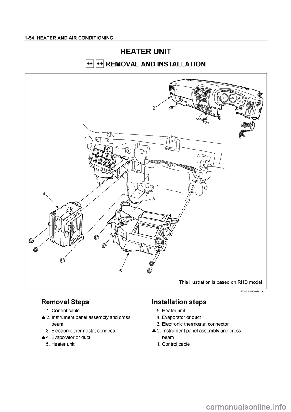
1-54 HEATER AND AIR CONDITIONING
HEATER UNIT
REMOVAL AND INSTALLATION
This illustration is based on RHD model
RTW310LF000501-X
Removal Steps
1. Control cable
� 2. Instrument panel assembly and cross
beam
3. Electronic thermostat connector
� 4. Evaporator or duct
5. Heater unit
Installation steps
5. Heater unit
4. Evaporator or duct
3. Electronic thermostat connector
� 2. Instrument panel assembly and cross
beam
1. Control cable
Page 3065 of 4264
HEATER AND AIR CONDITIONING 1-55
Important Operations – Removal
2. Instrument Panel Assembly and Cross Beam.
Refer to INSTRUMENT PANEL in CAB section.
4. Evaporator or Duct
Refer to “EVAPORATOR” or “DUCT” in this section.
Important Operation - Installation
2. Instrument Panel Assembly and Cross Beam
Adjust the heater control cables.
Refer to "CONTROL LEVER ASSEMBLY" in this section.
Page 3067 of 4264
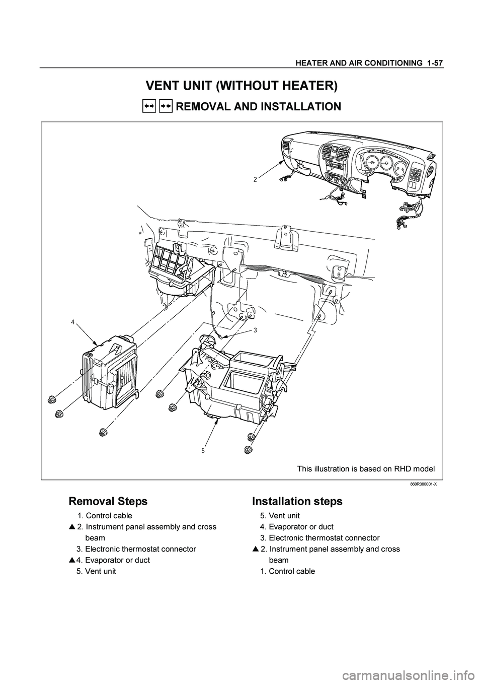
HEATER AND AIR CONDITIONING 1-57
VENT UNIT (WITHOUT HEATER)
REMOVAL AND INSTALLATION
This illustration is based on RHD model
860R300001-X
Removal Steps
1. Control cable
� 2. Instrument panel assembly and cross
beam
3. Electronic thermostat connector
� 4. Evaporator or duct
5. Vent unit
Installation steps
5. Vent unit
4. Evaporator or duct
3. Electronic thermostat connector
� 2. Instrument panel assembly and cross
beam
1. Control cable
Page 3068 of 4264
1-58 HEATER AND AIR CONDITIONING
Important Operations - Removal
2. Instrument Panel Assembly and Cross Beam.
Refer to INSTRUMENT PANEL in CAB section.
4. Evaporator or Duct
Refer to “EVAPORATOR” or “DUCT” in this section.
Important Operation - Installation
2. Instrument Panel Assembly and Cross Beam
Adjust the heater control cables.
Refer to "CONTROL LEVER ASSEMBLY" in this section.
Page 3075 of 4264
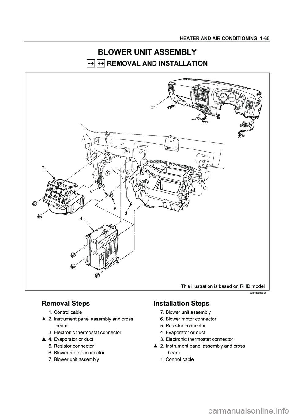
HEATER AND AIR CONDITIONING 1-65
BLOWER UNIT ASSEMBLY
REMOVAL AND INSTALLATION
This illustration is based on RHD model
873R300002-X
Removal Steps
1. Control cable
� 2. Instrument panel assembly and cross
beam
3. Electronic thermostat connector
� 4. Evaporator or duct
5. Resistor connector
6. Blower motor connector
7. Blower unit assembly
Installation Steps
7. Blower unit assembly
6. Blower motor connector
5. Resistor connector
4. Evaporator or duct
3. Electronic thermostat connector
� 2. Instrument panel assembly and cross
beam
1. Control cable
Page 3076 of 4264
1-66 HEATER AND AIR CONDITIONING
Important Operation - Installation
2. Instrument Panel Assembly and Cross Beam
Refer to “INSTRUMENT PANEL” in CAB section.
4. Evaporator or Duct
Refer to “EVAPORATOR” or “DUCT” in this section.
Important Operation - Installation
2. Instrument Panel Assembly and Cross Beam
Adjust the heater control cables.
Refer to “CONTOROL LEVER ASSEMBLY” in this section.
Page 3078 of 4264
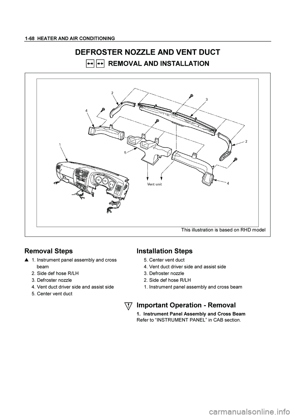
1-68 HEATER AND AIR CONDITIONING
DEFROSTER NOZZLE AND VENT DUCT
REMOVAL AND INSTALLATION
This illustration is based on RHD model
Removal Steps
� 1. Instrument panel assembly and cross
beam
2. Side def hose R/LH
3. Defroster nozzle
4. Vent duct driver side and assist side
5. Center vent duct
Installation Steps
5. Center vent duct
4. Vent duct driver side and assist side
3. Defroster nozzle
2. Side def hose R/LH
1. Instrument panel assembly and cross beam
Important Operation - Removal
1. Instrument Panel Assembly and Cross Beam
Refer to “INSTRUMENT PANEL ” in CAB section.