Page 4200 of 4264
7A4-26 UNIT REPAIR (JR405E)
No. Valve
nomenclature Diameter
(mm / in) Length
(mm / in)Configuration
14 Pressure relief ---- ----
15 Pressure
regulator 16.0 /
0.630 89.5 /
3.524
16 Low and reverse
brake fail (A) 10.0 /
0.394 52.0 /
2.047
17 Fail 12.0 /
0.472 53.5 /
2.106
18 Low and reverse
brake amp 12.0 /
0.472 55.5 /
2.185
19 2 – 4 brake fail
(A) 10.0 /
0.394 65.5 /
2.579
20 Low clutch amp
(B) 12.0 /
0.472 53.0 /
2.087
21 Torque
converter relief 10.0 /
0.394 37.4 /
1.472
22 2 – 4 brake
solenoid
accumulator 14.0 /
0.551 19.5 /
0.768
23 High clutch
accumulator 10.0 /
0.394 31.0 /
1.220
Page 4201 of 4264
 7A4-27
Spring specifications
No. Valve nomenclature Free length
(mm / in) Outside
diameter (mm
/ in) Linear
diameter (mm
/ in) Number of
coils
14 Pressure relief 49.")
UNIT REPAIR (JR405E) 7A4-27
Spring specifications
No. Valve nomenclature Free length
(mm / in) Outside
diameter (mm
/ in) Linear
diameter (mm
/ in) Number of
coils
14 Pressure relief 49.0 / 1.929 7.6 / 0.299 1.1 / 0.043 17.3
15 Pressure regulator 30.5 / 1.201 14.0 / 0.551 1.4 / 0.055 5.7
16 Low and reverse brake fail (A) 22.0 / 0.866 7.0 / 0.276 0.6 / 0.024 10.0
17 Fail 23.0 / 0.906 11.0 / 0.433 0.5 / 0.020 13.2
18 Low and reverse brake amp 19.5 / 0.768 7.9 / 0.311 0.5 / 0.020 6.9
19 2 – 4 brake fail (A) 24.8 / 0.976 8.5 / 0.335 0.9 / 0.035 7.8
20 Low clutch amp (B) 26.0 / 1.024 11.0 / 0.433 0.5 / 0.020 6.9
21
Torque converter relief More than 47.2
/ 1.858 9.2 / 0.362 1.6 / 0.063 20.2
22 2 – 4 brake solenoid accumulator 31.4 / 1.236 9.8 / 0.386 1.3 / 0.051 9.3
23 High clutch accumulator 51.0 / 2.008 6.5 / 0.256 0.8 / 0.031 23.5
Oil pressure switch
Apply compressed air (392 kPa/4.0 kg/cm2) to the oil pressure
switch to check the oil pressure switch continuity between the
connector and screw.
244L300011
Oil temperature sensor (harness assembly)
Check the oil temperature sensor resistance between harness
terminals 7 and 6 (ground).
Oil temperature sensor resistance: 2,400�
�� �2,600 ohms
(20�
�� �)
Solenoid
Measure the resistance of each solenoid.
Resistance:
Brown connector – 3.0�
�� �3.4 ohms (20�
�� �C)
Gray connector – 12.0�
�� �13.2 ohms (20�
�� �C)
White connector – 12.2�
�� �13.4 ohms (20�
�� �C)
Reassembly steps
� Coat the parts with ATF before installing them.
� Install the control valve to the control valve lower body.
� Install the oil filter to the control valve lower body.
Page 4205 of 4264
UNIT REPAIR (JR405E) 7A4-31
Reassembly steps
15PUMP18
1. O-ring (small)
Install new O-ring (small) to the oil pump housing.
16PUMP29
2. Outer rotor
3. Inner rotor Install the outer rotor and the inner rotor to the oil pump
housing.
17PUMP42
NOTE:
The identification mark on the inner rotor must be facing
the inside of the oil pump housing.
18PUMP07
4. Oil pump cover
5. Oil pump housing Install the oil pump cover to the oil pump housing.
Tighten the 8 bolts to the specified torque.
Torque: 9 N �
��
�
m (78 Ib �
��
�
in)
6. O-ring (large)
Install the O-ring (large) to the oil pump cover.
7. Seal ring Install the 4 seal rings to the oil pump cover.
Page 4233 of 4264
UNIT REPAIR (JR405E) 7A4-59
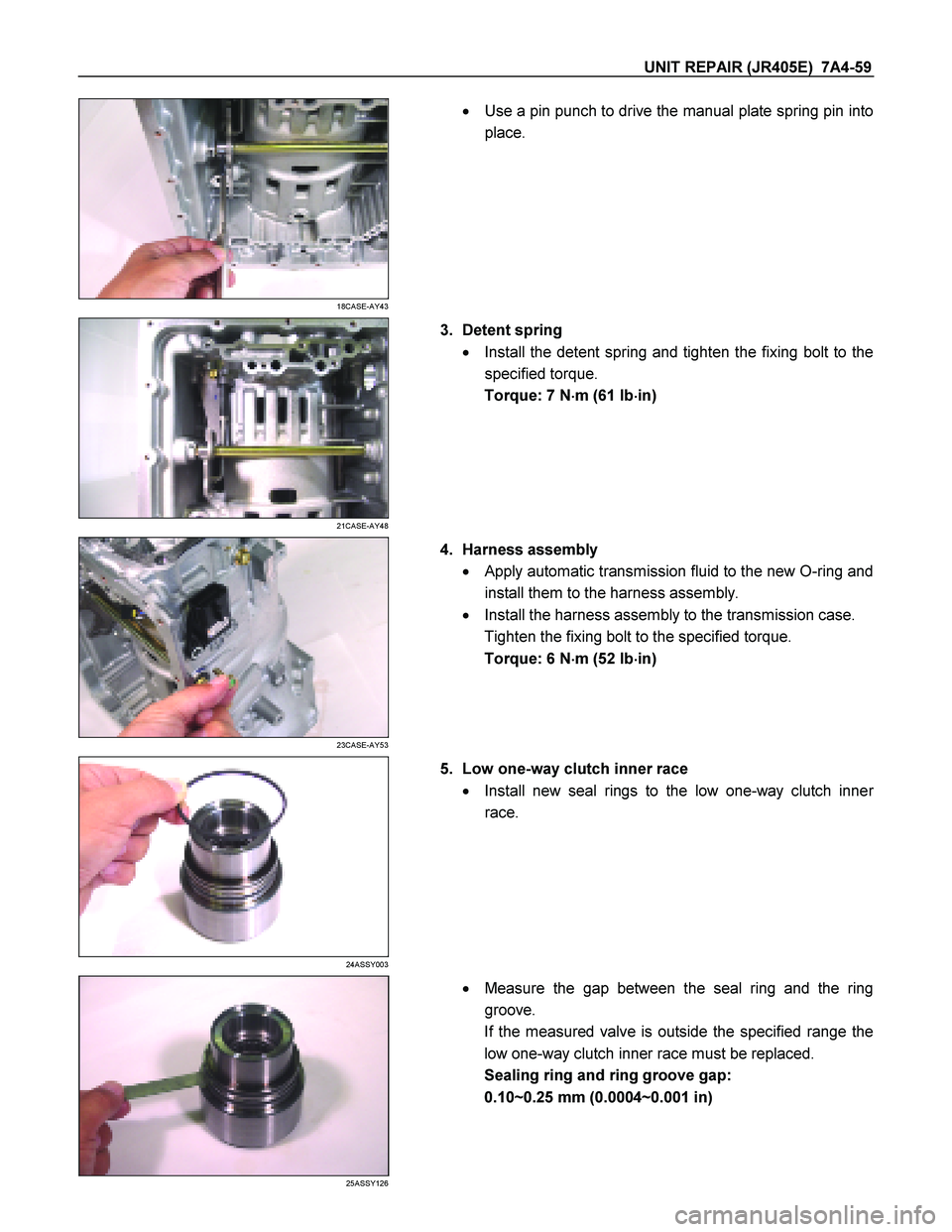
18CASE-AY43
�
Use a pin punch to drive the manual plate spring pin into
place.
21CASE-AY48
3. Detent spring
� Install the detent spring and tighten the fixing bolt to the
specified torque.
Torque: 7 N �
��
�
m (61 Ib �
��
�
in)
23CASE-AY53
4. Harness assembly
� Apply automatic transmission fluid to the new O-ring and
install them to the harness assembly.
� Install the harness assembly to the transmission case.
Tighten the fixing bolt to the specified torque.
Torque: 6 N �
��
�
m (52 Ib �
��
�
in)
24ASSY003
5. Low one-way clutch inner race
� Install new seal rings to the low one-way clutch inne
r
race.
25ASSY126
�
Measure the gap between the seal ring and the ring
groove.
If the measured valve is outside the specified range the
low one-way clutch inner race must be replaced.
Sealing ring and ring groove gap:
0.10~0.25 mm (0.0004~0.001 in)
Page 4235 of 4264
UNIT REPAIR (JR405E) 7A4-61
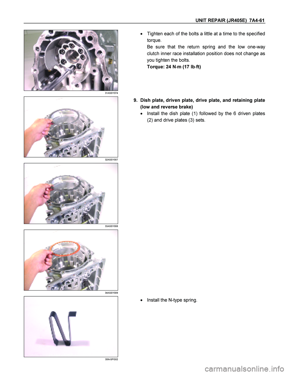
31ASSY074
�
Tighten each of the bolts a little at a time to the specified
torque.
Be sure that the return spring and the low one-way
clutch inner race installation position does not change as
you tighten the bolts.
Torque: 24 N �
��
�
m (17 Ib �
��
�
ft)
32ASSY007
9. Dish plate, driven plate, drive plate, and retaining plate
(low and reverse brake)
� Install the dish plate (1) followed by the 6 driven plates
(2) and drive plates (3) sets.
33ASSY008
34ASSY009
35N-SPG02
�
Install the N-type spring.
Page 4252 of 4264
7A4-78 UNIT REPAIR (JR405E)
30ASSY067
�
Apply ATF to the O-ring at the outside of the oil pump.
� Install the oil pump assembly to the transmission case.
�
Apply sealing agent (TB1215) to the threaded surfaces
of the 8 fixing bolts and tighten to the specified torque.
Torque: 58 N �
��
�
m (43 Ib �
��
�
ft)
31ASSY068
14.O-ring
Install a new O-ring to the input shaft.
32ASSY116
15.Converter housing
Install the converter housing and tighten the bolts to the
specified torque. Torque: 53 N �
��
�
m (39 Ib �
��
�
ft)
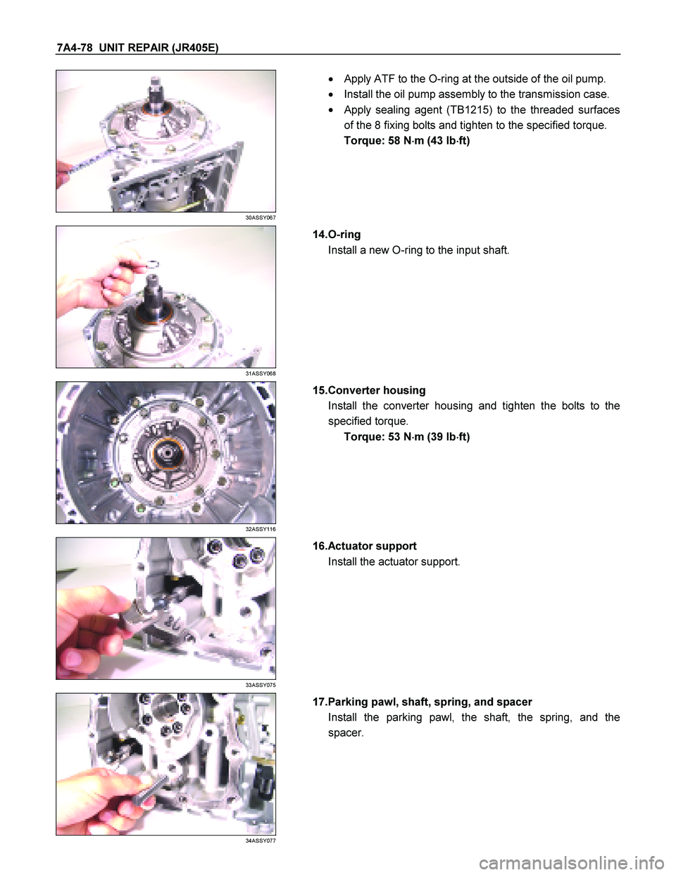
33ASSY075
16.Actuator support
Install the actuator support.
34ASSY077
17.Parking pawl, shaft, spring, and spacer
Install the parking pawl, the shaft, the spring, and the
spacer.
Page 4254 of 4264
7A4-80 UNIT REPAIR (JR405E)
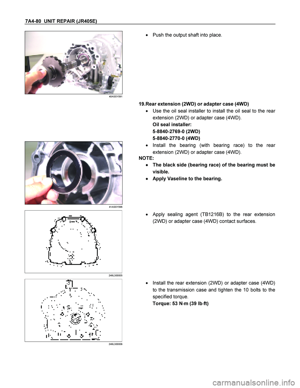
40ASSY091
�
Push the output shaft into place.
19.Rear extension (2WD) or adapter case (4WD)
� Use the oil seal installer to install the oil seal to the rea
r
extension (2WD) or adapter case (4WD).
Oil seal installer:
5-8840-2769-0 (2WD)
5-8840-2770-0 (4WD)
41ASSY096
�
Install the bearing (with bearing race) to the rear
extension (2WD) or adapter case (4WD).
NOTE:
�
� �
�
The black side (bearing race) of the bearing must be
visible.
�
� �
�
Apply Vaseline to the bearing.
249L300005
�
Apply sealing agent (TB1216B) to the rear extension
(2WD) or adapter case (4WD) contact surfaces.
249L300006
� Install the rear extension (2WD) or adapter case (4WD)
to the transmission case and tighten the 10 bolts to the
specified torque.
Torque: 53 N �
��
�
m (39 Ib �
��
�
ft)
Page 4255 of 4264
UNIT REPAIR (JR405E) 7A4-81
43ASSY119
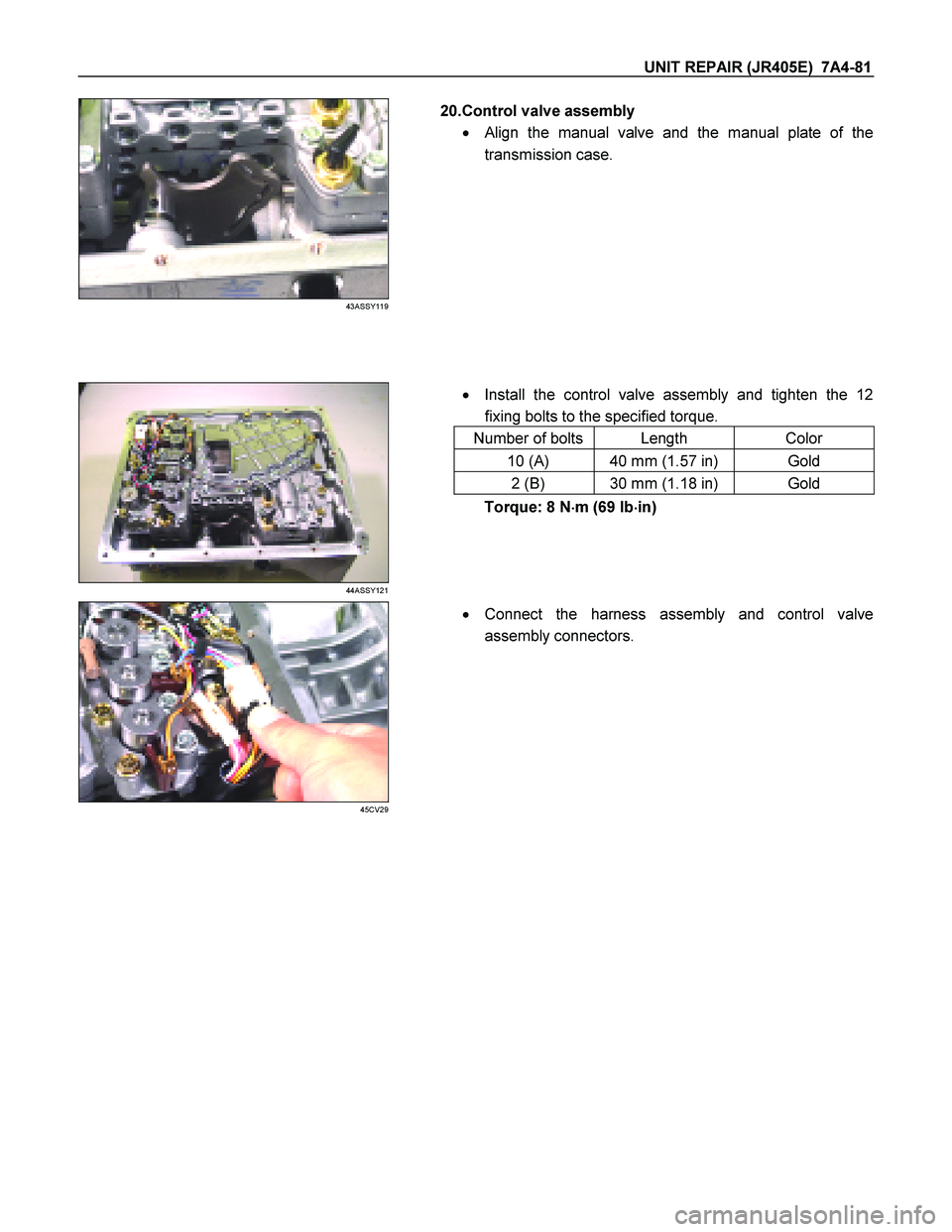
20.Control valve assembly
�
Align the manual valve and the manual plate of the
transmission case.
� Install the control valve assembly and tighten the 12
fixing bolts to the specified torque.
Number of bolts Length Color
10 (A) 40 mm (1.57 in) Gold
2 (B) 30 mm (1.18 in) Gold
44ASSY121
Torque: 8 N �
��
�
m (69 Ib �
��
�
in)
45CV29
�
Connect the harness assembly and control valve
assembly connectors.

No. Valve
nomenclature Diameter
(mm / in) Length
(mm / in)Configuration
14 Pressure relief ---- ----
15 Pressure
regulator 16.0 /
0.630 89.5 /
3.524
16 Low a")
 7A4-31
Reassembly steps
15PUMP18
1. O-ring (small)
Install new O-ring (small) to the oil pump housing.
16PUMP29
2. Outer rotor
3. Inner rotor")