Page 4173 of 4264
 7A3-21
4. Remove the shift cable from the transmission.
P1010068
5. Remove the rear propeller shaft assembly.
6. Loosen (do not remove) the nuts securing the
exhaust")
ON-VEHICLE SERVICE (JR405E) 7A3-21
4. Remove the shift cable from the transmission.
P1010068
5. Remove the rear propeller shaft assembly.
6. Loosen (do not remove) the nuts securing the
exhaust manifold and the exhaust pipe.
7. Disconnect the harness connectors from the
transmission.
8. Remove the fuel pipe bracket.
P1010013
P1010014
9. Remove the ATF level dipstick and tube.
10. Remove the undercover.
11. Rotate the ring gear and remove the 6 torque
converter bolts.
P1010016
12. Remove the automatic transmission fluid cooling
pipe.
P1010060
13. Place a jack beneath the engine to support it.
14. Remove the 3rd crossmember.
15. Remove the transmission mount.
16. Lower the jack beneath the engine slightly to tilt the
engine and transmission. Do not allow the radiato
r
and air conditioner hoses to stretch.
17. Remove the bolts attaching the transmission to the
engine.
18. Lower the transmission from beneath the vehicle.
Take care not to damage the breathers.
Install or Connect
1. Install the transmission to the engine and tighten the
bolts.
Bolt torque : M10 40 N·m (30 lb·ft)
M12 76 N·m (56 lb·ft)
2. Install the cable bracket to the transmission.
3. Connect the engine harness connectors.
Page 4174 of 4264
7A3-22 ON-VEHICLE SERVICE (JR405E)
4. Install the 3rd crossmember.
Bolt and Nut torque : 67 N·m (49 lb·ft)
Bolt torque : 50 N·m (37 lb·ft)
5. Install the automatic transmission fluid cooling pipe.
6. Install the torque converter bolts.
Bolt torque : 29 N·m (22 lb·ft)
7. Install the undercover.
Bolt torque : 9 N·m (78 lb·in)
8. Install the ATF level dipstick and tube.
9. Install the fuel hose bracket.
Bolt torque : 6 N·m (52 lb·in)
10. Tighten the nuts securing the exhaust manifold and
the exhaust pipe.
Bolt torque : 43 N·m (32 lb·ft)
11. Install the rear propeller shaft assembly.
Flange bolt torque : 63 N·m (46 lb·ft)
Center bearing bracket bolt torque :
69 N·m (51 lb·ft)
12. Install the shift cable.
13. Connect the negative battery cable.
14. Remove the safety stands.
15. Remove the wheels blocks.
Torque Specifications
RTW37ALF001501
Page 4177 of 4264
UNIT REPAIR (JR405E) 7A4-3
Disassembly steps
1. Torque converter
� Pull the torque converter free.
NOTE:
Place a pan beneath the torque converter to catch
automatic transmission fluid (ATF) spillage.
� Draining the ATF from the torque converter.
01ASSY101
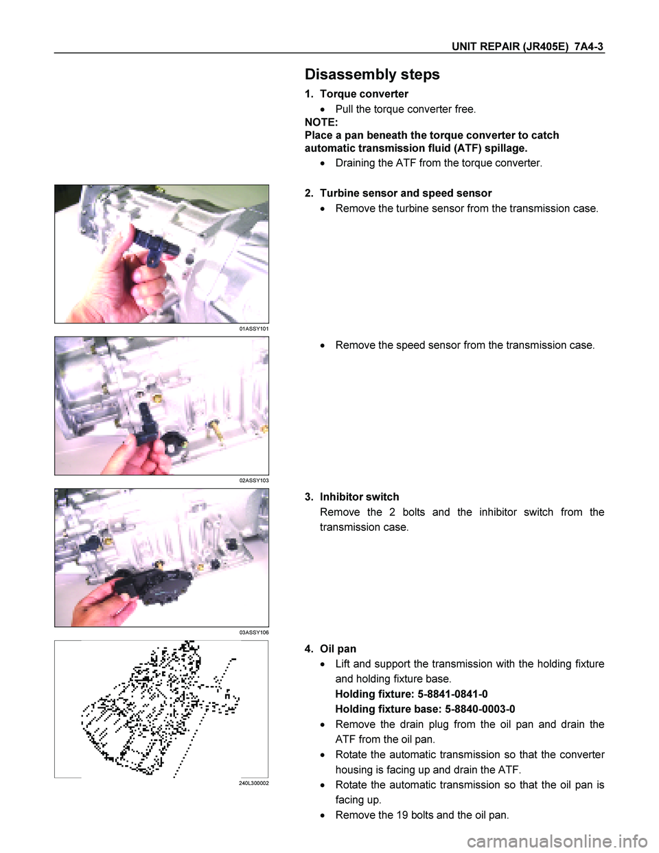
2. Turbine sensor and speed sensor
� Remove the turbine sensor from the transmission case.
02ASSY103
�
Remove the speed sensor from the transmission case.
03ASSY106
3. Inhibitor switch
Remove the 2 bolts and the inhibitor switch from the
transmission case.
240L300002
4. Oil pan
� Lift and support the transmission with the holding fixture
and holding fixture base.
Holding fixture: 5-8841-0841-0
Holding fixture base: 5-8840-0003-0
� Remove the drain plug from the oil pan and drain the
ATF from the oil pan.
� Rotate the automatic transmission so that the converte
r
housing is facing up and drain the ATF.
� Rotate the automatic transmission so that the oil pan is
facing up.
� Remove the 19 bolts and the oil pan.
Page 4187 of 4264
UNIT REPAIR (JR405E) 7A4-13
Reassembly steps
Coat the parts with ATF before installing them.
11CV18
1. Control valve upper body
2. Control valve lower body
3. Separation plate
Assembly the control valve upper body, the lower body, and
the separation plate.
Tighten the bolts to the specified torque.
244L300002
Page 4188 of 4264
7A4-14 UNIT REPAIR (JR405E)
Number Length (Color)
Control valve rocket
bolts and nuts (A) 2 (Plus 2 nuts) 50 mm (1.97 in) (Gold)
Upper body and
lower body fixing
bolts
(B) 2 45 mm (1.77 in) (Silver)
(C) 13 35 mm (1.38 in) (Silver)
Line pressure
solenoid fixing bolt
(D) 1 16 mm (0.63 in) (Gold)
Torque: 8 N�
�� �m (69 Ib�
�� �in)
Page 4190 of 4264
7A4-16 UNIT REPAIR (JR405E)
12CV19
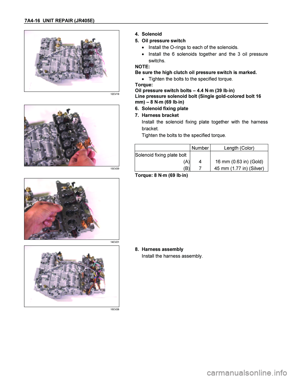
4. Solenoid
5. Oil pressure switch � Install the O-rings to each of the solenoids.
� Install the 6 solenoids together and the 3 oil pressure
switchs.
NOTE:
Be sure the high clutch oil pressure switch is marked.
� Tighten the bolts to the specified torque.
Torque:
Oil pressure switch bolts – 4.4 N �
��
�
m (39 Ib �
��
�
in)
Line pressure solenoid bolt (Single gold-colored bolt 16
mm) – 8 N �
��
�
m (69 Ib �
��
�
in)
6. Solenoid fixing plate
7. Harness bracket Install the solenoid fixing plate together with the harness
bracket.
Tighten the bolts to the specified torque.
Number Length (Color)
Solenoid fixing plate bolt
(A) 4 16 mm (0.63 in) (Gold)
(B) 7 45 mm (1.77 in) (Silver)
13CV20
Torque: 8 N �
��
�
m (69 Ib �
��
�
in)
14CV21
15CV26
8. Harness assembly
Install the harness assembly.
Page 4191 of 4264
UNIT REPAIR (JR405E) 7A4-17
9. Oil strainer Install the oil strainer.
Tighten the bolts to the specified torque.
Number Length (Color)
Oil strainer bolt
(C) 9 13 mm (0.51 in) (Silver)
(D) 4 45 mm (1.77 in) (Silver)
16CV40
Torque: 8 N �
��
�
m (69 Ib �
��
�
in)
Page 4197 of 4264
UNIT REPAIR (JR405E) 7A4-23
CONTROL VALVE LOWER BODY
10CV11
Legend
1. Retainer plate, spring, and steel ball
2. Retainer plate, plug, spring, and
pressure regulator valve
3. Retainer plate, spring, and high clutch
accumulator
4. Retainer plate, plug, low and reverse
brake fail valve A, and spring
5. Retainer plate, plug, spring, and fail
valve
6. Retainer plate, plug, low and reverse
brake amp valve, and spring
7. Oil pressure switch
8. Oil filter
9. Solenoid
10. Line pressure solenoid
11. Lock-up solenoid
12. Harness bracket
13. Solenoid fixing plate
14. Harness assembly
15. Retainer plate, plug, spring, and 2-4
brake fail valve A
16. Retainer plate, plug, spring, and low
clutch amp valve B
17. Retainer plate, spring, and torque
converter relief valve
18. Oil strainer
19. Control valve lower body
20. Retainer plate, spring, and 2-4 brake
solenoid accumulator
21. Oil pressure switch

4. Install the 3rd crossmember.
Bolt and Nut torque : 67 N·m (49 lb·ft)
Bolt torque : 50 N·m (37 lb·ft)
5. Install the automatic transmission fluid")
 7A4-13
Reassembly steps
Coat the parts with ATF before installing them.
11CV18
1. Control valve upper body
2. Control valve lower body
3. Separation plate
Assemb")

Number Length (Color)
Control valve rocket
bolts and nuts (A) 2 (Plus 2 nuts) 50 mm (1.97 in) (Gold)
Upper body and
lower body fixing
bolts
(B) 2 45 mm (1.77")
 7A4-17
9. Oil strainer Install the oil strainer.
Tighten the bolts to the specified torque.
Number Length (Color)
Oil strainer bolt
(C) 9 13 mm (0.51 in) (Silver)")
 7A4-23
CONTROL VALVE LOWER BODY
10CV11
Legend
1. Retainer plate, spring, and steel ball
2. Retainer plate, plug, spring, and
pressure regulator valve
3. Retain")