Page 3583 of 4264
WHEELS AND TIRES 3E-11
Shoulder wear (generally
wear develops on outer
shoulder).
Camber or toe-in
incorrect.Shoulder wear
caused by repeated
hard-cornering.
Wear on shoulders at points
opposed to each other.
Tire or wheel out of
round or distorted.Play in bearings or
ball joint.
Premature wear on
shoulders.
Flexing of tire excessive due
to under-inflation.
One-sided feather edging.
Wear caused by
repeated hard-
cornering.Camber or toe-in
incorrect.
Page 3584 of 4264
3E-12 WHEELS AND TIRES
MEMO
Page 3591 of 4264
TRANSFER CASE 7D-3
General Description
RUW34DLF000701
The transfer case is used to provide a means of
providing power flow to the front axle. The transfer case
also provides a means of disconnecting the front axle,
providing better fuel economy and quieter operation
when the vehicle is driven on improved roads where
four wheel drive is not required. In addition, the transfer
case provides an additional gear reduction when placed
in low range, which is useful when difficult off-road
conditions are encountered.
Use the 4WD switch on the center cluster panel to
select the drive range. The 4WD indicator lamp will be
lit when 4WD is selected.
Page 3621 of 4264
TRANSFER CASE 7D-33
Main Data and Specifications
General Specifications
Type Synchronized type gears shifting between the 2 and 4 wheel drive mode.
Planetary type gears shifting between “low" and “high".
Control method Remote control with the button switch on the instrument panel for gears
shifting among “2H" , “4H" and “4L".
Gear ratio High; 1.000
Low; 2.482
Oil capacity 1.3 lit. (1.37 U.S. quart)
Type of lubricant BESCO GEAR OIL TRANSAXLE (5W-30)
Refer to chart in Section 0
Torque Specifications
N�m (kg�m/lb ft)
RTW47DLF000201
Page 3629 of 4264
TRANSFER CONTROL SYSTEM 7D1-3
General Description
RTW47DLF000301
Transfer Position and Drive Mode
Three drive modes can be selected through operation of 4WD switch.
Transfer Position 4WD SWITCH Mode Drive mode
2H RWD Rear wheel drive
HIGH
4H 4WD (HIGH) High-speed mechanical
lock-up four wheel drive
LOW 4L 4WD (LOW) Low-speed mechanical
lock-up four wheel drive
NEUTRAL 2H & 4L (10 Sec) NEUTRAL Towed by other vehicle
Page 3630 of 4264

7D1-4 TRANSFER CONTROL SYSTEM
Summary of transfer control system
The transfer control system switches between the 2-wheel
drive (2H), 4-wheel drive high-speed (4H), 4-wheel drive low-
speed (4L), and neutral positions electrically when the driver
operate the switches.
This system has following functions.
1. Connection or disconnection of drive force distribution to
the front wheel front shaft (axle shaft) (The drive force
distribution to the front propeller is connected o
r
disconnected with the motor actuator.)
2. Try to repeat the connection or disconnection of the front
wheel drive function as described above.
3. Option: Shift on the fly type only.
Instruction of connection or disconnection of the drive force
transmission between the front wheel axle (axle shaft) and
front wheel
(The motor actuator connects or disconnects the left front
wheel ad front wheel axle (axle shaft).).
4. Shifting of auxiliary transmission gears, connection o
r
disconnection of wheel and engine drive force (4H, 4L,
neutral).
5. Operation of indicator on the instrument panel.
6. Transmission of position signal to other controllers.
Page 3660 of 4264

7D1-34 TRANSFER CONTROL SYSTEM
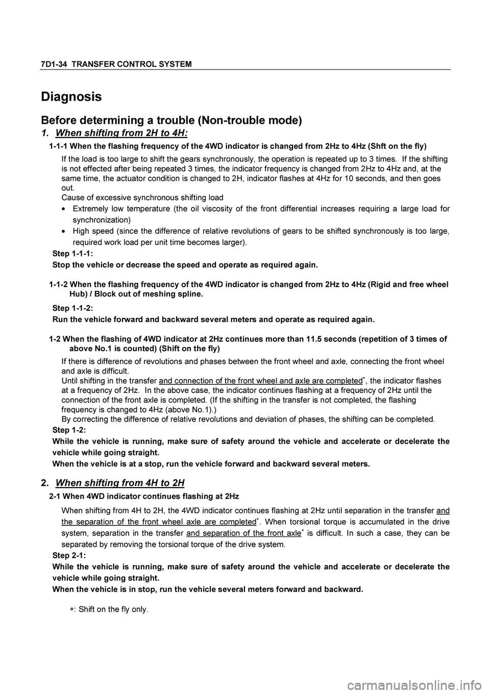
Diagnosis
Before determining a trouble (Non-trouble mode)
1. When shifting from 2H to 4H:
1-1-1 When the flashing frequency of the 4WD indicator is changed from 2Hz to 4Hz (Shft on the fly)
If the load is too large to shift the gears synchronously, the operation is repeated up to 3 times. If the shifting
is not effected after being repeated 3 times, the indicator frequency is changed from 2Hz to 4Hz and, at the
same time, the actuator condition is changed to 2H, indicator flashes at 4Hz for 10 seconds, and then goes
out.
Cause of excessive synchronous shifting load
�
Extremely low temperature (the oil viscosity of the front differential increases requiring a large load for
synchronization)
� High speed (since the difference of relative revolutions of gears to be shifted synchronously is too large,
required work load per unit time becomes larger).
Step 1-1-1:
Stop the vehicle or decrease the speed and operate as required again.
1-1-2 When the flashing frequency of the 4WD indicator is changed from 2Hz to 4Hz (Rigid and free wheel
Hub) / Block out of meshing spline.
Step 1-1-2:
Run the vehicle forward and backward several meters and operate as required again.
1-2 When the flashing of 4WD indicator at 2Hz continues more than 11.5 seconds (repetition of 3 times of
above No.1 is counted) (Shift on the fly)
If there is difference of revolutions and phases between the front wheel and axle, connecting the front wheel
and axle is difficult.
Until shifting in the transfer and connection of the front wheel and axle are completed
�, the indicator flashes
at a frequency of 2Hz. In the above case, the indicator continues flashing at a frequency of 2Hz until the
connection of the front axle is completed. (If the shifting in the transfer is not completed, the flashing
frequency is changed to 4Hz (above No.1).)
By correcting the difference of relative revolutions and deviation of phases, the shifting can be completed.
Step 1-2:
While the vehicle is running, make sure of safety around the vehicle and accelerate or decelerate the
vehicle while going straight.
When the vehicle is at a stop, run the vehicle forward and backward several meters.
2.
When shifting from 4H to 2H
2-1 When 4WD indicator continues flashing at 2Hz
When shifting from 4H to 2H, the 4WD indicator continues flashing at 2Hz until separation in the transfer and
the separation of the front wheel axle are completed�. When torsional torque is accumulated in the drive
system, separation in the transfer and separation of the front axle� is difficult. In such a case, they can be
separated by removing the torsional torque of the drive system.
Step 2-1:
While the vehicle is running, make sure of safety around the vehicle and accelerate or decelerate the
vehicle while going straight.
When the vehicle is in stop, run the vehicle several meters forward and backward.
�
: Shift on the fly only.
Page 3733 of 4264

TRANSMISSION CONTROL SYSTEM (AW30–40LE) (V6 3.5L) 7A2-53
The DTC will be cleared from history when the
vehicle has achieved 40 warm-up cycles without a
failure reported.
After more than 1 second has elapsed after the
ignition key has been turned “ON", short between
No.11 and No.4 (ground) of DLC (Data Link
Connector). Then, after 1 second, but within 6
seconds, discontinue shorting.
Diagnostic Aids
Inspect the wiring for poor electrical connection at
the TCM. Look for possible bent, backed out,
deformed or damaged terminals. Check for weak
terminal tension as well. Also check for a chafed wire
that could short to bare metal or other wiring.
Inspect for a broken wire inside the insulation.
When diagnosing for a possible intermittent short o
r
open condition, move the wiring harness while
observing test equipment for a change.
Check output speed sensor for proper mounting and
adjustment.
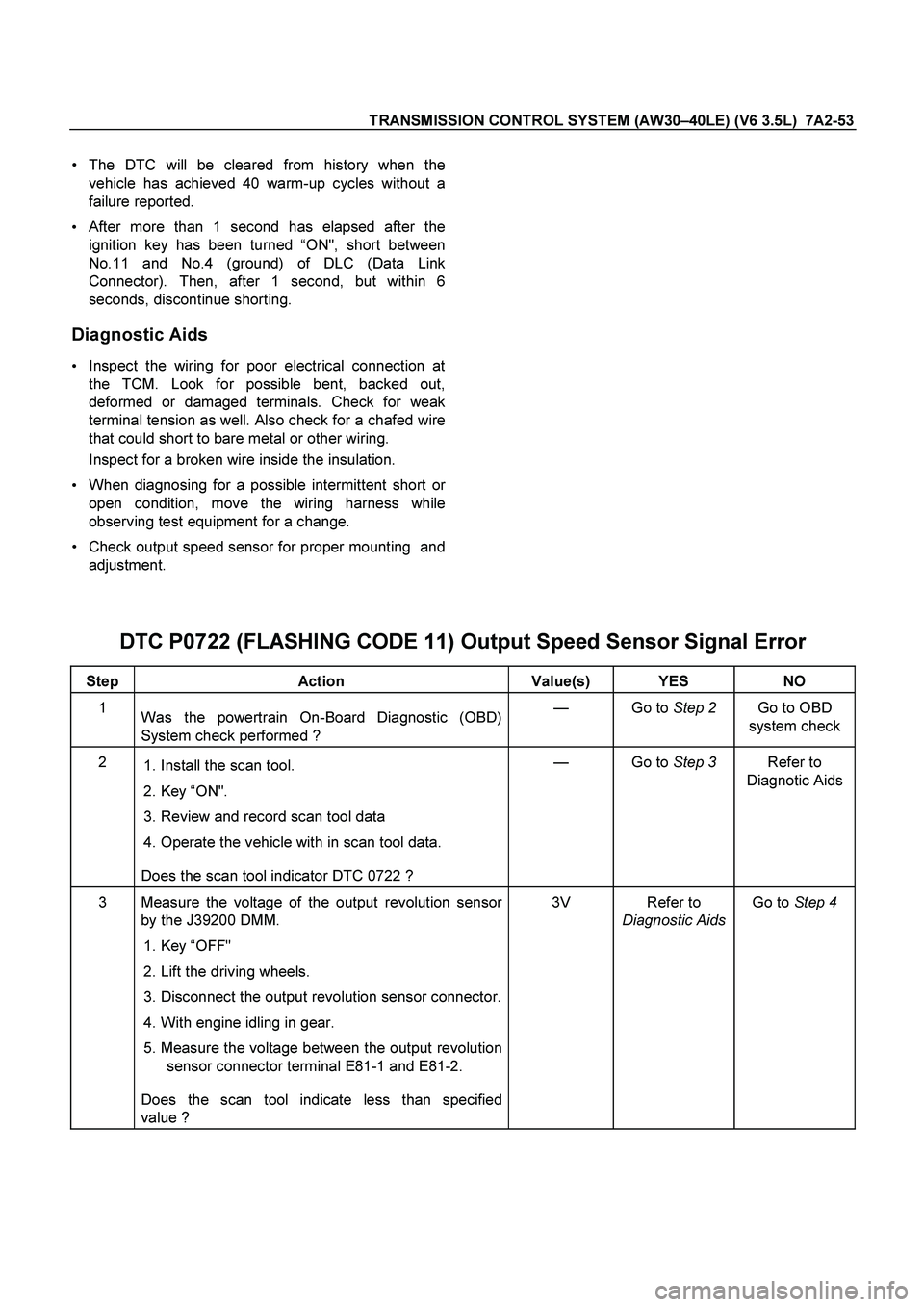
DTC P0722 (FLASHING CODE 11) Output Speed Sensor Signal Error
Step Action Value(s) YES NO
1
Was the powertrain On-Board Diagnostic (OBD)
System check performed ? — Go to Step 2 Go to OBD
system check
2
1. Install the scan tool.
2. Key “ON".
3. Review and record scan tool data
4. Operate the vehicle with in scan tool data.
Does the scan tool indicator DTC 0722 ? — Go to Step 3 Refer to
Diagnotic Aids
3 Measure the voltage of the output revolution sensor
by the J39200 DMM.
1. Key “OFF"
2. Lift the driving wheels.
3. Disconnect the output revolution sensor connector.
4. With engine idling in gear.
5. Measure the voltage between the output revolution
sensor connector terminal E81-1 and E81-2.
Does the scan tool indicate less than specified
value ? 3V Refer to
Diagnostic Aids Go to Step 4