Page 3769 of 4264

ON-VEHICLE SERVICE (AW30 –40LE) 7A3-13
Measure Stall Speed
1. Chock the four wheels.
2. Mount an engine tachometer.
3. Fully apply the parking brake.
4. Step down strongly on the brake pedal with your left foot.
5. Start the engine.
6. Turn off the A/C.
7. Shift into the “D" range. Step all the way down on
the accelerator pedal with your right foot. Quickl
y
read the highest engine rpm.
Stall speed: 2100 �
� �
�
150 rpm
8. Perform the same test in the “R" range.
Evaluation
1. If the engine speed is the same for both ranges but
lower than the specified value:
Engine output is insufficient.
Stator one-way clutch is not operating properly.
NOTE: If more than 600 rpm below the specified value,
the torque converter could be faulty.
2. If the stall speed in “D" range is higher than
specified:
Line pressure too low
Forward clutch slipping
No.2 one-way clutch not operating properly
3. If the stall speed in “R" range is higher than
specified:
Line pressure too low
Direct clutch slipping
No.3 brake slipping
4. If the stall speed in the “R" and “D" ranges are
higher than specified:
Line pressure too low
Improper fluid level
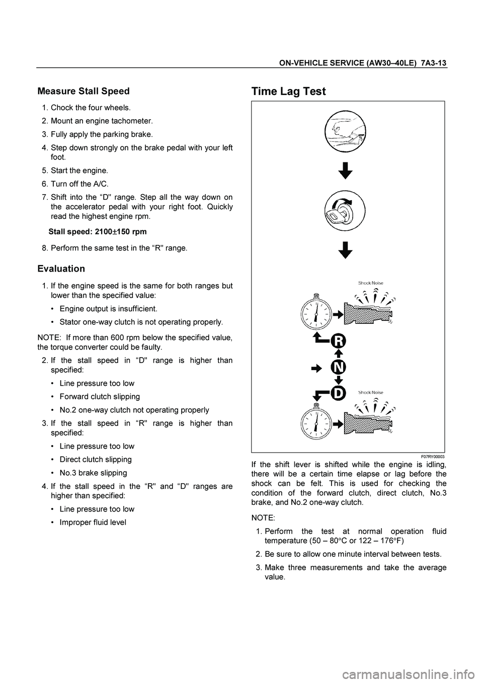
Time Lag Test
F07RY00003
If the shift lever is shifted while the engine is idling,
there will be a certain time elapse or lag before the
shock can be felt. This is used for checking the
condition of the forward clutch, direct clutch, No.3
brake, and No.2 one-way clutch.
NOTE:
1. Perform the test at normal operation fluid
temperature (50 – 80 �C or 122 – 176 �F)
2. Be sure to allow one minute interval between tests.
3. Make three measurements and take the average value.
Page 3771 of 4264

ON-VEHICLE SERVICE (AW30 –40LE) 7A3-15
Measure Line Pressure
1. Fully apply the parking brake and chock the four
wheels.
2. Start the engine and check idling rpm.
3. Shift into “D" range, step down strongly on the brake
pedal with your left foot and, while manipulating the
accelerator pedal with the right foot, measure the
line pressures at the engine speeds specified in the
table.
4. In the same manner, perform the test in “R" range.
Line pressure kPa (kg/cm2/psi) Engine
speed “D" range “R" range
Idling 323 – 382
(3.3 – 3.9/47 – 55) 500 – 598
(5.1 – 6.1/73 – 87)
Stall 1,137 – 1,274 (11.6–13.0/165–185) 1,499 – 1,833
(15.3–18.7/218–266)
Evaluation
1. If the measured values at all ranges are higher than
specified:
Pressure control solenoid defective
Primary regulator valve defective
2. If the measured values at all ranges are lower than
specified:
Primary regulator valve defective
Oil pump defective
Pressure control solenoid defective
3. If pressure is low in “D" range only:
“ D" range circuit fluid leakage
4. If pressure is low in “R" range only:
“ R" range circuit fluid leakage
Road Test
NOTE: Perform the test at normal operation fluid
temperature (50 – 80 �
C or 122 – 176 �
F).
“D" Range Test in “NORMAL", and
“POWER" Pattern Ranges
Shift into the “D" range and hold the accelerator pedal
constant at the 50% and 100% throttle valve opening
positions.
Push in one of the pattern selector buttons and check
the following:
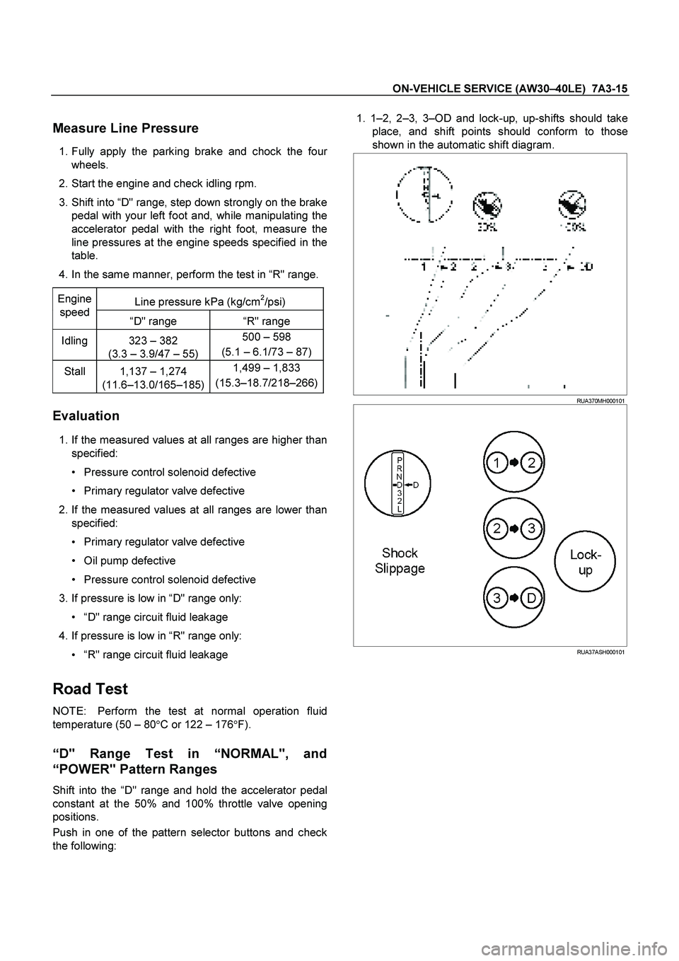
1. 1 –2, 2 –3, 3 –OD and lock-up, up-shifts should take
place, and shift points should conform to those
shown in the automatic shift diagram.
RUA370MH000101
RUA37ASH000101
Page 3784 of 4264
7A3-28 ON-VEHICLE SERVICE (AW30 –40LE)
Select Lever
RTW37ALF001101
Legend
(6) Base plate
(1) Rear console
(7) Grooved pin
(2) Front console
(8) Spring plate
(3) Select lever knob
(9) Lever assembly
(4) Upper housing
(10) Sleeve
(5) Lamp assembly
Remove or Disconnect
1.
Block the wheels.
2.
Disconnect the negative battery cable.
3.
Remove the rear console and the front console.
4.
Remove the 2 screws fixing the select lever knob.
5.
Remove the knob together with the knob button and
spring from the lever.
6.
Turn the sleeve counterclockwise to remove it. Make
a note of the number of turns required to free the
sleeve.
7.
Remove the harness connectors from the base plate.
Page 3787 of 4264
ON-VEHICLE SERVICE (AW30 –40LE) 7A3-31
Shift Cable
RTW47ALF000101
Legend
(5) Bracket
(1) Select lever
(6) Clip
(2) Shift cable retaining pawl
(7) Shift cable
(3) Manual shaft select lever
(8) Select lever base
(4) Adjuster
Remove or Disconnect
1.
Block the wheels.
2.
Disconnect the negative battery cable.
3.
Move the select lever to the “N ” position.
4.
Remove the rear console and front console.
5.
Disconnect the shift cable from the select lever.
6.
Press on the shift cable retaining pawl to remove the
cable from the select lever base.
7.
Disconnect the shift cable from the transmission
side.
8.
Remove the shift cable from the bracket.
9.
Pull the shift cable free from the bottom of the
vehicle.
Page 3788 of 4264

7A3-32 ON-VEHICLE SERVICE (AW30 –40LE)
Install or Connect
1.
Install the shift cable toward the inside of the cabin
from the bottom of the vehicle.
2.
Push the shift cable into the select lever base.
3.
Connect the shift cable to the select lever.
4.
Fix the shift cable to the bracket.
Install the clip on the marking of shift cable.
5.
Check that the select lever is in the “N ” position.
6.
Check that the transmission is in the “N ” position.
249R300002
7.
Slide the cover in the direction shown by the arrow
(1).
8.
Use an ordinary screwdriver to move the lock piece
from the position indicated by the arrow (2). Continue
to move the lock piece until the adjuster position
begins to change.
P1010012
9.
Connect the shift cable to the manual shaft select
lever at the transmission side.
10.
Insert the lock piece to the adjuster (cable length
adjustment).
11.
Slide the cover on the adjuster and secure lock
piece.
P1010016-2
11.
Press the select lever knob button 5 times.
Then check that the select lever moves smoothly to each of its positions.
13.
Check that the shift position indicated by the select
lever and the actual shift position are the same.
14.
Install the front console and rear console.
15.
Connect the negative battery cable.
16.
Remove the wheel blocks.
Page 4028 of 4264

7A2-36 DIAGNOSIS (JR405E)
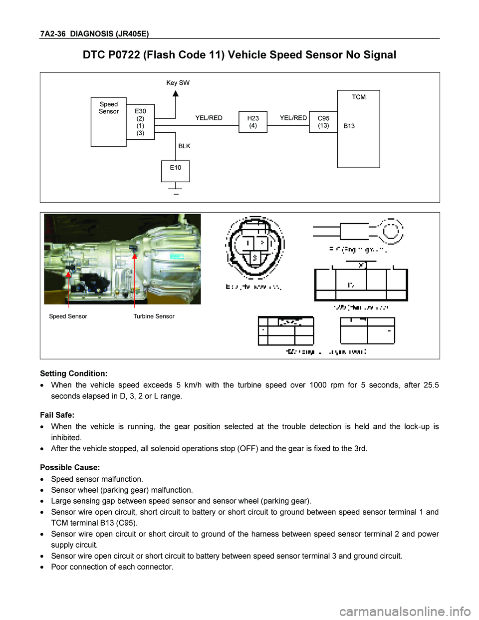
DTC P0722 (Flash Code 11) Vehicle Speed Sensor No Signal
Speed
Sensor
TCM
B13
H23
(4)C95
(13)E30
(2)
(1)
(3)
E10
Key SW
YEL/RED
BLK YEL/RED
Speed Sensor Turbine Sensor
Setting Condition:
� When the vehicle speed exceeds 5 km/h with the turbine speed over 1000 rpm for 5 seconds, after 25.5
seconds elapsed in D, 3, 2 or L range.
Fail Safe:
� When the vehicle is running, the gear position selected at the trouble detection is held and the lock-up is
inhibited.
� After the vehicle stopped, all solenoid operations stop (OFF) and the gear is fixed to the 3rd.
Possible Cause:
� Speed sensor malfunction.
� Sensor wheel (parking gear) malfunction.
� Large sensing gap between speed sensor and sensor wheel (parking gear).
� Sensor wire open circuit, short circuit to battery or short circuit to ground between speed sensor terminal 1 and
TCM terminal B13 (C95).
� Sensor wire open circuit or short circuit to ground of the harness between speed sensor terminal 2 and power
supply circuit.
� Sensor wire open circuit or short circuit to battery between speed sensor terminal 3 and ground circuit.
� Poor connection of each connector.
Page 4030 of 4264
7A2-38 DIAGNOSIS (JR405E)
DTC P0727 (Flash Code 13) Engine Revolution Sensor No Signal
RED
TDC
Sensor TCM
A7
C94 (7)
BLK/RED
WHT
C56
(27)
E9
(1)
(2)
(3)
C57 (98)
(90)
(101)
ECM
C56 (ECM-A)
Setting Condition:
� The engine speed becomes 0 rpm for 2 seconds while the vehicle is running at the over 40 km/h.
Fail Safe:
� Lock-up is inhibited.
Possible Cause:
� Crank position sensor malfunction.
� Sensor wheel (flywheel) malfunction.
� Large sensing gap between speed sensor and sensor wheel (flywheel).
� Faulty input signal from crank position sensor to ECM.
� Signal wire open circuit or short circuit to battery between ECM A24 and TCM terminal A7 (C94).
� Poor connection of each connector.
Reference:
When the engine speed 2000rpm, following signal is outputted.
Measurement terminal: A7 (C94) and B5 (C95)
-AC range by circuit tester: Approximately 6.2V
-Oscilloscope: Following wave form can be found.
Page 4032 of 4264

7A2-40 DIAGNOSIS (JR405E)
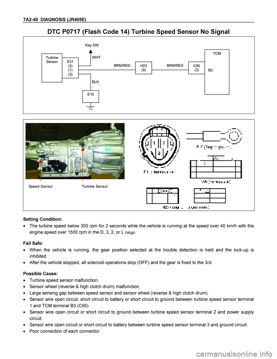
DTC P0717 (Flash Code 14) Turbine Speed Sensor No Signal
Turbine
Sensor TCM
B3
H23 (9)C95 (3) E31 (2)
(1)
(3)
E10
Key SW
BRN/RED
WHT
BLK BRN/RED
Speed Sensor Turbine Sensor
Setting Condition:
� The turbine speed below 300 rpm for 2 seconds while the vehicle is running at the speed over 40 km/h with the
engine speed over 1500 rpm in the D, 3, 2, or L range.
Fail Safe:
� When the vehicle is running, the gear position selected at the trouble detection is held and the lock-up is
inhibited.
� After the vehicle stopped, all solenoid operations stop (OFF) and the gear is fixed to the 3rd.
Possible Cause:
� Turbine speed sensor malfunction.
� Sensor wheel (reverse & high clutch drum) malfunction.
� Large sensing gap between speed sensor and sensor wheel (reverse & high clutch drum).
� Sensor wire open circuit, short circuit to battery or short circuit to ground between turbine speed sensor terminal
1 and TCM terminal B3 (C95).
� Sensor wire open circuit or short circuit to ground between turbine speed sensor terminal 2 and power supply
circuit.
� Sensor wire open circuit or short circuit to battery between turbine speed sensor terminal 3 and ground circuit.
� Poor connection of each connector.