Page 4132 of 4264
7A2-140 DIAGNOSIS (JR405E)
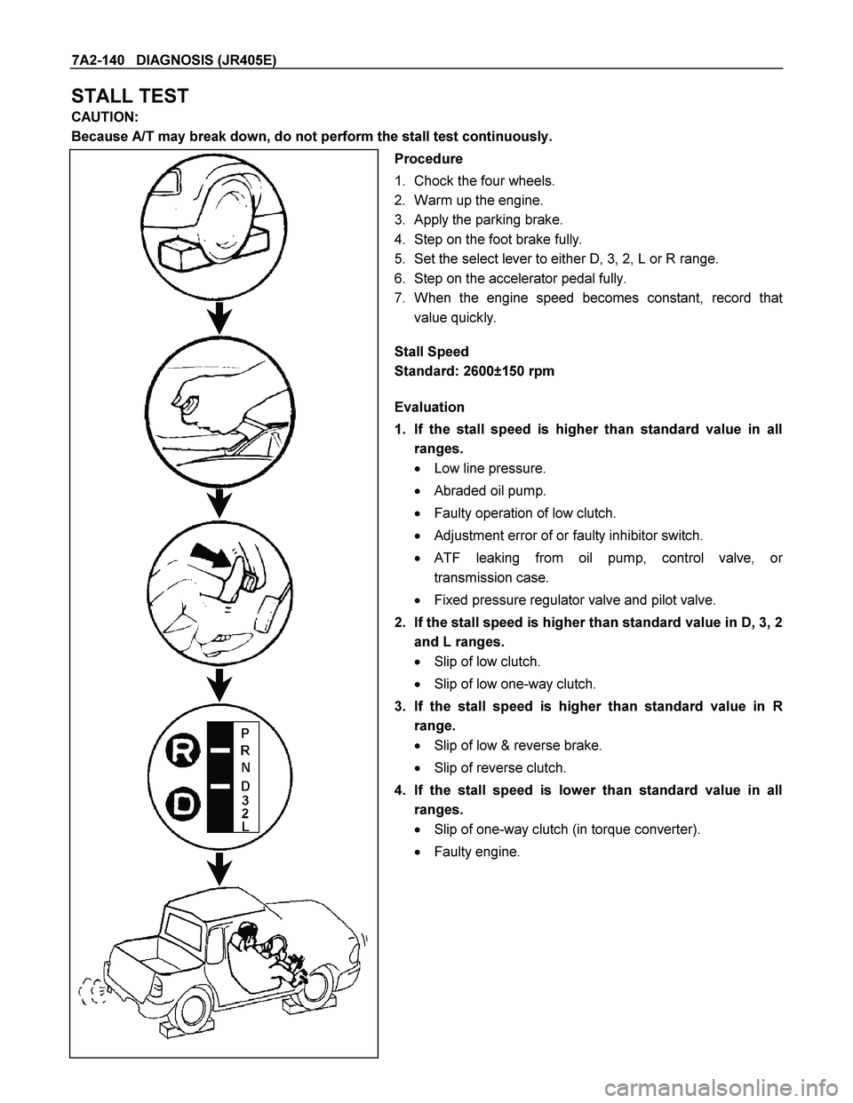
STALL TEST
CAUTION:
Because A/T may break down, do not perform the stall test continuously.
Procedure
1. Chock the four wheels.
2. Warm up the engine.
3. Apply the parking brake.
4. Step on the foot brake fully.
5. Set the select lever to either D, 3, 2, L or R range.
6. Step on the accelerator pedal fully.
7. When the engine speed becomes constant, record tha
t
value quickly.
Stall Speed
Standard: 2600±150 rpm
Evaluation
1. If the stall speed is higher than standard value in all
ranges.
� Low line pressure.
� Abraded oil pump.
� Faulty operation of low clutch.
� Adjustment error of or faulty inhibitor switch.
�
ATF leaking from oil pump, control valve, or
transmission case.
� Fixed pressure regulator valve and pilot valve.
2. If the stall speed is higher than standard value in D, 3, 2
and L ranges.
� Slip of low clutch.
� Slip of low one-way clutch.
3. If the stall speed is higher than standard value in
R
range.
� Slip of low & reverse brake.
� Slip of reverse clutch.
4. If the stall speed is lower than standard value in all
ranges.
� Slip of one-way clutch (in torque converter).
� Faulty engine.
Page 4133 of 4264
DIAGNOSIS (JR405E) 7A2-141
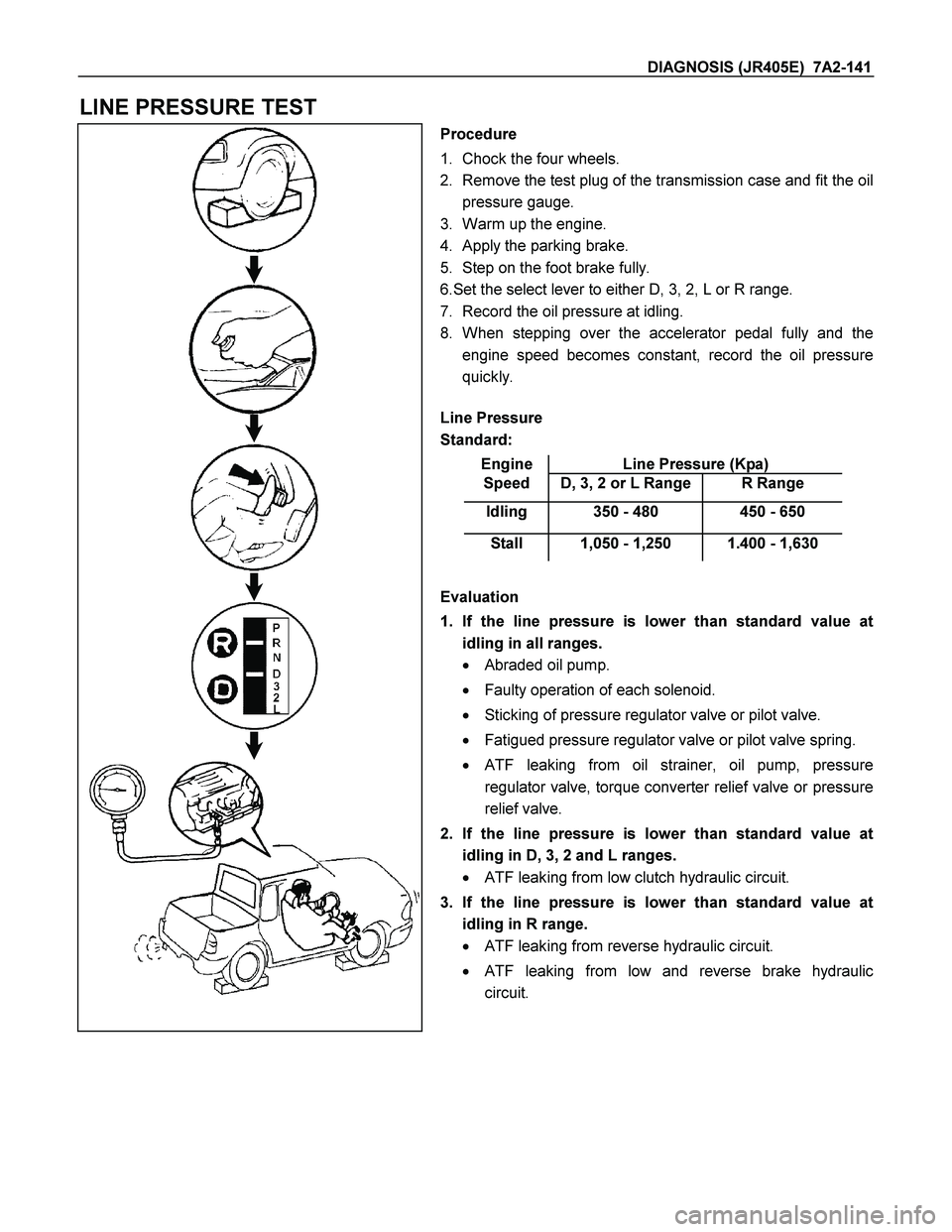
LINE PRESSURE TEST
Procedure
1. Chock the four wheels.
2. Remove the test plug of the transmission case and fit the oil
pressure gauge.
3. Warm up the engine.
4. Apply the parking brake.
5. Step on the foot brake fully.
6.Set the select lever to either D, 3, 2, L or R range.
7. Record the oil pressure at idling.
8. When stepping over the accelerator pedal fully and the
engine speed becomes constant, record the oil pressure
quickly.
Line Pressure
Standard:
Engine Line Pressure (Kpa)
Speed D, 3, 2 or L Range R Range
Idling 350 - 480 450 - 650
Stall 1,050 - 1,250 1.400 - 1,630
Evaluation
1. If the line pressure is lower than standard value at
idling in all ranges.
� Abraded oil pump.
� Faulty operation of each solenoid.
� Sticking of pressure regulator valve or pilot valve.
� Fatigued pressure regulator valve or pilot valve spring.
�
ATF leaking from oil strainer, oil pump, pressure
regulator valve, torque converter relief valve or pressure
relief valve.
2. If the line pressure is lower than standard value at
idling in D, 3, 2 and L ranges.
� ATF leaking from low clutch hydraulic circuit.
3. If the line pressure is lower than standard value at
idling in R range.
� ATF leaking from reverse hydraulic circuit.
� ATF leaking from low and reverse brake hydraulic
circuit.
Page 4135 of 4264
DIAGNOSIS (JR405E) 7A2-143
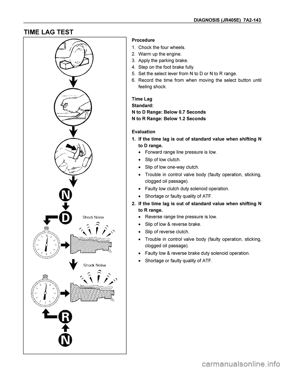
TIME LAG TEST
Procedure
1. Chock the four wheels.
2. Warm up the engine.
3. Apply the parking brake.
4. Step on the foot brake fully.
5. Set the select lever from N to D or N to R range.
6. Record the time from when moving the select button until
feeling shock.
Time Lag
Standard:
N to D Range: Below 0.7 Seconds
N to R Range: Below 1.2 Seconds
Evaluation
1. If the time lag is out of standard value when shifting N
to D range.
� Forward range line pressure is low.
� Slip of low clutch.
� Slip of low one-way clutch.
� Trouble in control valve body (faulty operation, sticking,
clogged oil passage).
� Faulty low clutch duty solenoid operation.
� Shortage or faulty quality of ATF.
2. If the time lag is out of standard value when shifting N
to R range.
� Reverse range line pressure is low.
� Slip of low & reverse brake.
� Slip of reverse clutch.
� Trouble in control valve body (faulty operation, sticking,
clogged oil passage).
� Faulty low & reverse brake duty solenoid operation.
� Shortage or faulty quality of ATF.
Page 4155 of 4264
ON-VEHICLE SERVICE (JR405E) 7A3-3
Cold Level
The vehicle must not have been driven so that the
temperature reaches around 20�C (68�F) before the
cold level check is made.
1. Park the vehicle on a level surface.
2. Apply the parking brake firmly.
3. Start the engine and allow it to warm up.
The engine coolant temperature gauge needle
should be midway between the “C” mark and “H”
mark.
4. Let the engine run at idle.
Move the select lever slowly through all the gea
r
ranges.
Stop in each range just long enough for the
transmission to engage.
5. Return the select lever either “P” or “N”.
6. Remove the ATF level dipstick.
7. Wipe the dipstick clean with a paper towel.
8. Reinsert the dipstick and wait several seconds.
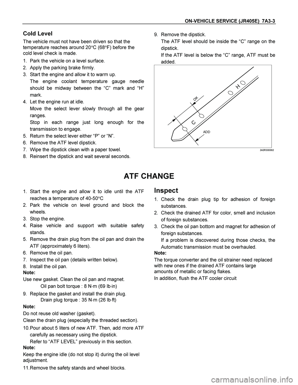
9. Remove the dipstick.
The ATF level should be inside the “C”range on the
dipstick.
If the ATF level is below the “C” range, ATF must be
added.
242R300002
ATF CHANGE
1. Start the engine and allow it to idle until the ATF
reaches a temperature of 40-50�C
2. Park the vehicle on level ground and block the
wheels.
3. Stop the engine.
4. Raise vehicle and support with suitable safety
stands.
5. Remove the drain plug from the oil pan and drain the
ATF (approximately 6 liters).
6. Remove the oil pan.
7. Inspect the oil pan (details written below).
8. Install the oil pan.
Note:
Use new gasket. Clean the oil pan and magnet.
Oil pan bolt torque : 8 N�m (69 lb�in)
9. Replace the gasket and install the drain plug.
Drain plug torque : 35 N�m (26 lb�ft)
Note:
Do not reuse old washer (gasket).
Clean the drain plug (especially the threaded section).
10. Pour about 5 liters of new ATF. Then, add more ATF
carefully as necessary using the dipstick.
Refer to “ATF LEVEL” previously in this section.
Note:
Keep the engine idle (do not stop it) during the oil level
adjustment.
11. Remove the safety stands and wheel blocks. Inspect
1. Check the drain plug tip for adhesion of foreign
substances.
2. Check the drained ATF for color, smell and inclusion
of foreign substances.
3. Check the oil pan bottom and magnet for adhesion o
f
foreign substances.
If a problem is discovered during those checks, the
Automatic transmission must be overhauled.
Note:
The torque converter and the oil strainer need replaced
with new ones if the drained ATF contains large
amounts of metallic or facing flakes.
In addition, flush the ATF cooler circuit
Page 4158 of 4264
7A3-6 ON-VEHICLE SERVICE (JR405E)
INHIBITOR SWITCH
The inhibitor switch is attached to the right side of the
transmission.
Inspect
1. Block the wheels.
2. Disconnect the negative battery cable.
3. Disconnect the harness connectors.
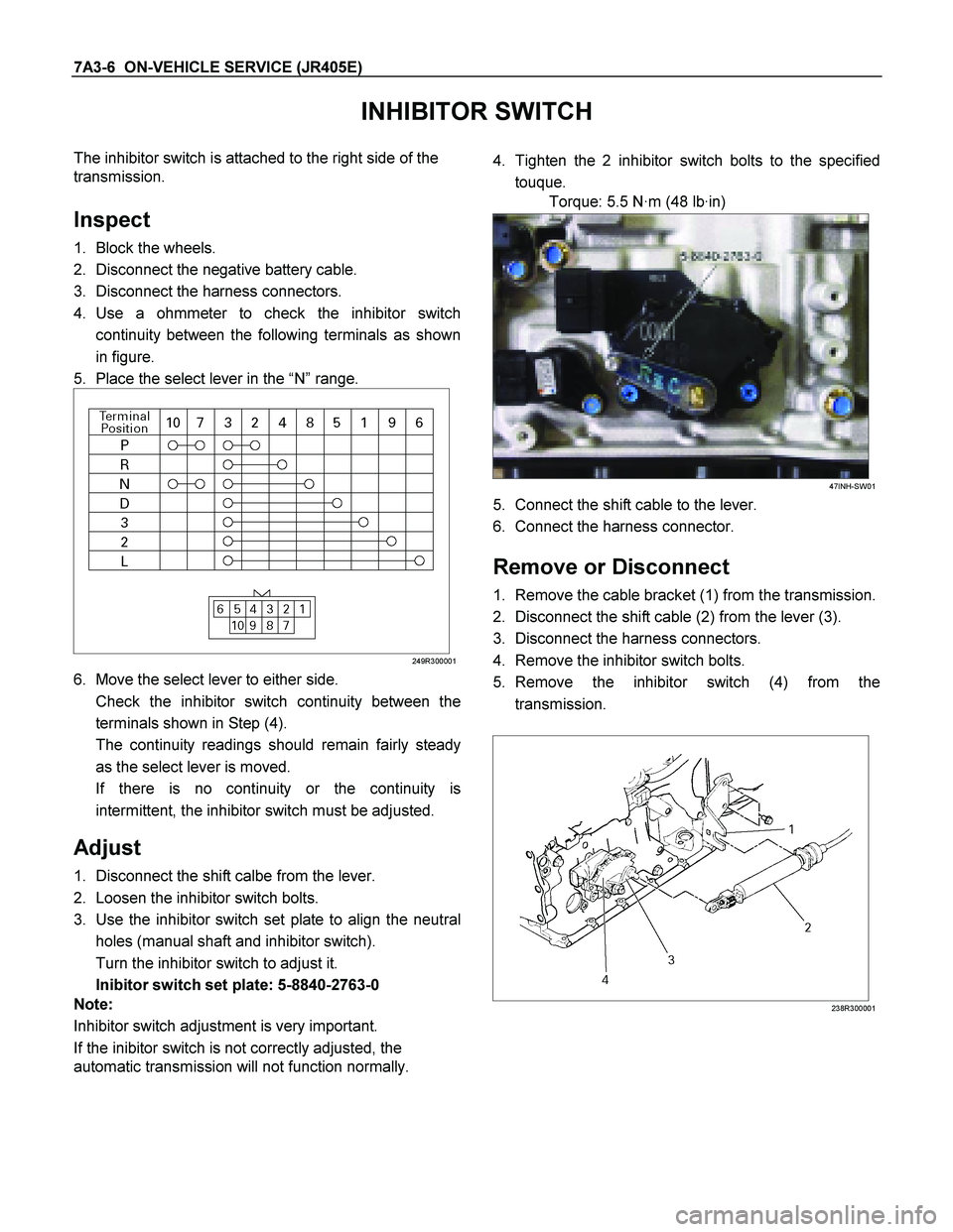
4. Use a ohmmeter to check the inhibitor switch
continuity between the following terminals as shown
in figure.
5. Place the select lever in the “N” range.
249R300001
6. Move the select lever to either side.
Check the inhibitor switch continuity between the
terminals shown in Step (4).
The continuity readings should remain fairly steady
as the select lever is moved.
If there is no continuity or the continuity is
intermittent, the inhibitor switch must be adjusted.
Adjust
1. Disconnect the shift calbe from the lever.
2. Loosen the inhibitor switch bolts.
3. Use the inhibitor switch set plate to align the neutral
holes (manual shaft and inhibitor switch).
Turn the inhibitor switch to adjust it.
Inibitor switch set plate: 5-8840-2763-0
Note:
Inhibitor switch adjustment is very important.
If the inibitor switch is not correctly adjusted, the
automatic transmission will not function normally.
4. Tighten the 2 inhibitor switch bolts to the specified
touque.
Torque: 5.5 N·m (48 lb·in)
47INH-SW01
5. Connect the shift cable to the lever.
6. Connect the harness connector.
Remove or Disconnect
1. Remove the cable bracket (1) from the transmission.
2. Disconnect the shift cable (2) from the lever (3).
3. Disconnect the harness connectors.
4. Remove the inhibitor switch bolts.
5. Remove the inhibitor switch (4) from the
transmission.
238R300001
Page 4159 of 4264
ON-VEHICLE SERVICE (JR405E) 7A3-7
Install or Connect
1. Install the inhibitor switch (4) to the transmission.
Temporarily tighten the inhibitor switch bolts.
2. Move the manual shaft select lever to the “N” range.
249R300002
3. Use the inhibitor switch set plate to align the neutral
holes (manual shaft and inhibitor switch).
Turn the inhibitor switch to adjust it.
Inhibitor switch set plate: 5-8840-2763-0
Note:
Inhibitor switch adjustment is very important.
If the inhibitor switch is not correctly adjusted, the
automatic transmission will not function normally.
4. Tighten the 2 inhibitor switch bolts to the specified
torque.
Torque: 5.5 N·m (48 lb·in)
47INH-SW01
5. Install the cable bracket (1) to the transmission.
6. Connect the shift cable (2) to the lever (3).
7. Connect the harness connector.
8. Connect the negative battery cable.
9. Remove the wheel blocks.
Page 4161 of 4264
ON-VEHICLE SERVICE (JR405E) 7A3-9
TURBINE SENSOR
The turbine sensor is attached to the right side of the
transmission.
Inspect
1. During the driving at speed of 20km/h (12mph) with
“L” range in low gear, measure the voltage between
the TCM connector terminals (B3) and (B5) with a
digital voltmeter.
Standard voltage : approx. 7V (AC range)
2. If the voltage is out of the standard value, check the
turbine sensor pole piece for presence of foreign
materials and the turbine sensor cable for short o
r
open circuit.
Result of the inspection is normal, replace the
turbine sensor.
Torque: 6 N·m (52 lb·in)
POWER AND 3RD START SWITCH
Inspect
1. Block the wheels.
2. Disconnect the negative battery cable.
3. Pry out the switch from the floor console.
4. Disconnect the harness connector.
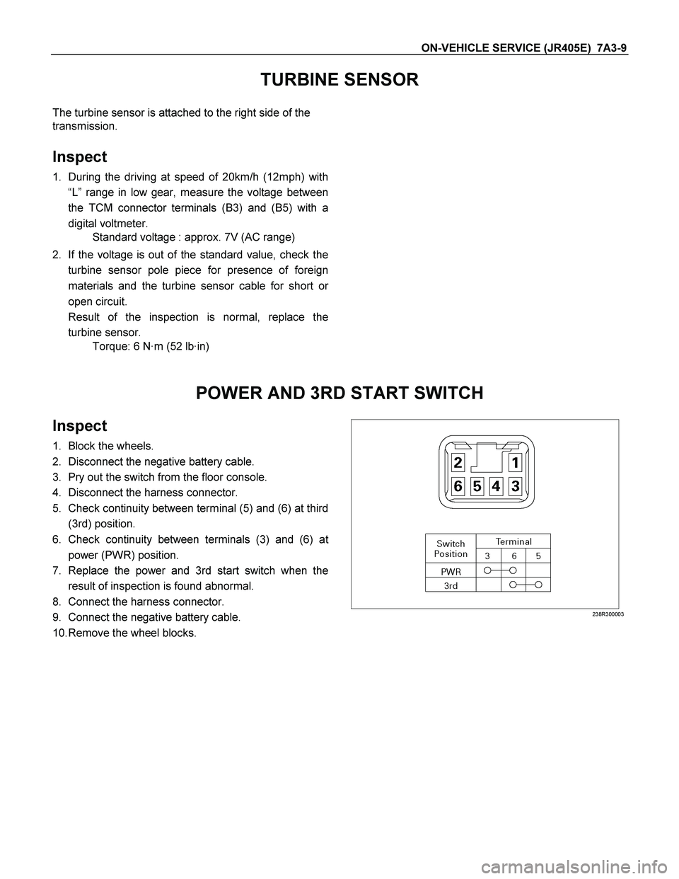
5. Check continuity between terminal (5) and (6) at third
(3rd) position.
6. Check continuity between terminals (3) and (6) a
t
power (PWR) position.
7. Replace the power and 3rd start switch when the
result of inspection is found abnormal.
8. Connect the harness connector.
9. Connect the negative battery cable.
10. Remove the wheel blocks.
238R300003
Page 4162 of 4264
7A3-10 ON-VEHICLE SERVICE (JR405E)
SELECT LEVER
RTW37ALF001101
Legend
1. Rear console
2. Front console
3. Select lever knob
4. Upper housing
5 Lamp assembly
6 Base plate
7 Grooved pin
8 Spring plate
9 Lever assembly
10 Sleeve
Remove or Disconnect
1. Block the wheels.
2. Disconnect the negative battery cable.
3. Remove the rear console and the front console.
4. Remove the 2 screws fixing the select lever knob.
5. Remove the knob together with the knob button and
spring from the lever.
6. Turn the sleeve counterclockwise to remove it. Make
a note of the number of turns required to free the
sleeve.
7. Remove the harness connectors from the base plate.
8. Remove the upper housing (held in place by 4
latched fasteners).
9. Remove the spring plate.