Page 2647 of 4264

ENGINE DRIVEABILITY AND EMISSIONS 6E–71
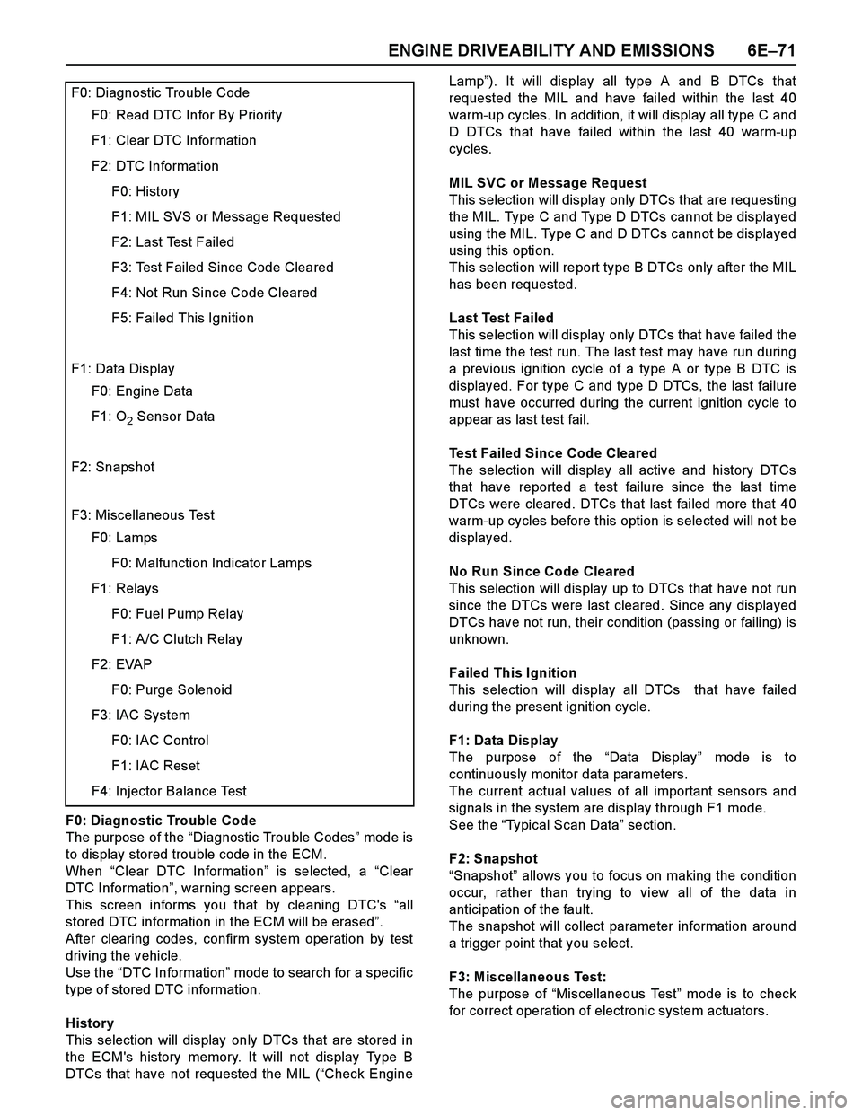
F0: Diagnostic Trouble Code
The purpose of the “Diagnostic Trouble Codes” mod e i s
to display stored trouble code in the ECM.
When “Clear DTC Information” is selected, a “Clear
DTC Information”, warning screen appears.
This screen informs you that by cleaning DTC's “all
stored DTC information in the ECM will be erased”.
After clearing codes, confirm system operation by test
driving the vehicle.
Use the “DTC Information” mode to search for a specific
type of stored DTC information.
History
This selection will display only DTCs that are stored in
the ECM's history memory. It will not display Type B
DTCs that have not requested the MIL (“Check EngineLamp”). It will display all type A and B DTCs that
requested the MIL and have failed within the last 40
warm-up cycles. In addition, it will display all type C and
D DTCs that have failed within the last 40 warm-up
cycles.
MIL SVC or Message Request
This selection will display only DTCs that are requesting
the MIL. Type C and Type D DTCs cannot be displayed
using the MIL. Type C and D DTCs cannot be displayed
using this option.
This selection will report type B DTCs only after the MIL
has been requested.
Last Test Failed
This selection will display only DTCs that have failed the
last time the test run. The last test may have run during
a previous ignition cycle of a type A or type B DTC is
displayed. For type C and type D DTCs, the last failure
must have occurred during the current ignition cycle to
appear as last test fail.
Test Failed Since Code Cleared
The selection will display all active and history DTCs
that have reported a test failure since the last time
DTCs were cleared. DTCs that last failed more that 40
warm-up cycles before this option is selected will not be
displayed.
No Run Since Code Cleared
This selection will display up to DTCs that have not run
since the DTCs were last cleared. Since any displayed
DTCs have not run, their condition (passing or failing) is
unknown.
Failed This Ignition
This selection will display all DTCs that have failed
during the present ignition cycle.
F1: Data Display
The purpose of the “Data Display” mode is to
continuously monitor data parameters.
The current actual values of all important sensors and
signals in the system are display through F1 mode.
See the “Typical Scan Data” section.
F2: Snapshot
“Snapshot” allows you to focus on making the condition
occur, rather than trying to view all of the data in
anticipation of the fault.
The snapshot will collect parameter information around
a trigger point that you select.
F3: Miscellaneous Test:
The purpose of “Miscellaneous Test” mode is to check
for correct operation of electronic system actuators.
F0: Diagnostic Trouble Code
F0: Read DTC Infor By Priority
F1: Clear DTC Information
F2: DTC Information
F0: History
F1: MIL SVS or Message Requested
F2: Last Test Failed
F3: Test Failed Since Code Cleared
F4: Not Run Since Code Cleared
F5: Failed This Ignition
F1: Data Display
F0: Engine Data
F1: O2 Sensor Data
F2: Snapshot
F3: Miscellaneous Test
F0: Lamps
F0: Malfunction Indicator Lamps
F1: Relays
F0: Fuel Pump Relay
F1: A/C Clutch Relay
F2: EVAP
F0: Purge Solenoid
F3: IAC System
F0: IAC Control
F1: IAC Reset
F4: Injector Balance Test
Page 2660 of 4264

6E–84 ENGINE DRIVEABILITY AND EMISSIONS
SERVICE PROGRAMMING SYSTEM (SPS)
The procedure to program the control unit by using the
Service Programming System (SPS) software contained
in TIS2000 is ex plained below.
NOTE:
If the Engine Control Module (ECM) was
programmed, the Immobilizer System must be
linked to the ECM: Refer to section 11
“Immobilizer System-ECM replacement” for the
ECM/Immobilizer linking procedure.
Should Tech2 display "SPS Procedure was not
successful", engine will not start, but no DTCs
are present, low battery voltage or poor electrical
connections should be the primary suspects.
Perform the SPS procedure again after rectifying
the fault/s.IMPORTANT:
Perform the following checks before attempting to
program the control unit:
The Tech2 PCMCIA card is programmed with The
latest software release.
The latest release of TIS2000 is loaded on the PC.
The vehicle battery is fully charged.
The control unit to be programmed is connected
to the vehicle.
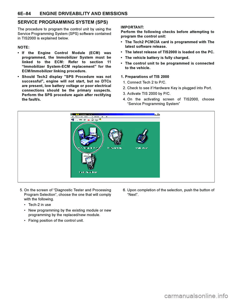
1. Preparations of TIS 2000
1. Connect Tech 2 to P/C.
2. Check to see if Hardware Key is plugged into Port.
3. Activate TIS 2000 by P/C.
4. On the activating screen of TIS2000, choose
“Service Programming System”
5. On the screen of “Diagnostic Tester and Processing
Program Selection”, choose the one that will comply
with the following.
Tech-2 in use
New programming by the ex isting module or new
programming by the replaced/new module.
Fix ing position of the control unit.6. Upon completion of the selection, push the button of
“Nex t”.
Page 2669 of 4264
ENGINE DRIVEABILITY AND EMISSIONS 6E–93
13 Replace the ECM.
Is the action complete?
IMPORTANT: The replacement ECM must be
programmed. Refer to section of the Service
Programming System (SPS) in this manual.
Following ECM programming, the immobilizer system
(if equipped) must be linked to the ECM. Refer to
section 11 “Immobilizer System-ECM replacement” for
the ECM/Immobilizer linking procedure.—Veri fy repai r— Step Action Value(s) Yes No
Page 2671 of 4264

ENGINE DRIVEABILITY AND EMISSIONS 6E–95
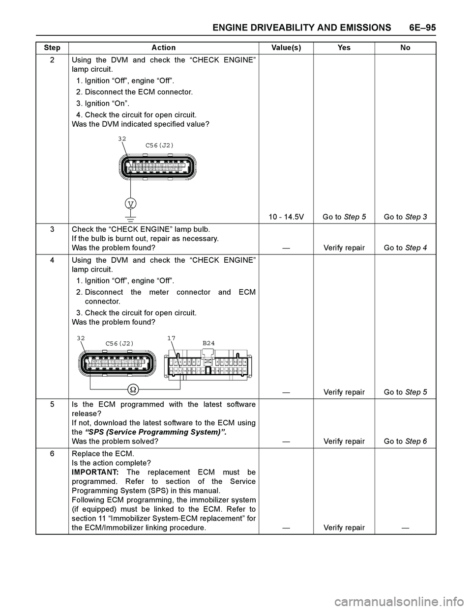
2 Using the DVM and check the “CHECK ENGINE”
lamp circuit.
1. Ignition “Off”, engine “Off”.
2. Disconnect the ECM connector.
3. Ignition “On”.
4. Check the circuit for open circuit.
Was the DVM indicated specified value?
10 - 14.5V Go to Step 5Go to Step 3
3 Check the “CHECK ENGINE” lamp bulb.
If the bulb is burnt out, repair as necessary.
Was the problem found?—Verify repair Go to Step 4
4 Using the DVM and check the “CHECK ENGINE”
lamp circuit.
1. Ignition “Off”, engine “Off”.
2. Disconnect the meter connector and ECM
connector.
3. Check the circuit for open circuit.
Was the problem found?
—Verify repair Go to Step 5
5 Is the ECM programmed with the latest software
release?
If not, download the latest software to the ECM using
the “SPS (Service Programming System)”.
Was the problem solved?—Verify repair Go to Step 6
6 Replace the ECM.
Is the action complete?
IMPORTANT: The replacement ECM must be
programmed. Refer to section of the Service
Programming System (SPS) in this manual.
Following ECM programming, the immobilizer system
(if equipped) must be linked to the ECM. Refer to
section 11 “Immobilizer System-ECM replacement” for
the ECM/Immobilizer linking procedure.—Veri fy repai r— Step Action Value(s) Yes No
V
32C56(J2)
3217C56(J2)B24
Page 2673 of 4264
ENGINE DRIVEABILITY AND EMISSIONS 6E–97
2 Using the DVM and check the “CHECK ENGINE”
lamp circuit.
1. Ignition “Off”, engine “Off”.
2. Disconnect the meter connector and ECM
connector.
3. Check the circuit for short to ground circuit.
Was the problem found?
—Verify repair Go to Step 3
3 Replace the meter assembly.
Is the action complete?—Veri fy repai r—
4 Is the ECM programmed with the latest software
release?
If not, download the latest software to the ECM using
the “SPS (Service Programming System)”.
Was the problem solved?—Verify repair Go to Step 5
5 Replace the ECM.
Is the action complete?
IMPORTANT: The replacement ECM must be
programmed. Refer to section of the Service
Programming System (SPS) in this manual.
Following ECM programming, the immobilizer system
(if equipped) must be linked to the ECM. Refer to
section 11 “Immobilizer System-ECM replacement” for
the ECM/Immobilizer linking procedure.—Veri fy repai r— Step Action Value(s) Yes No
32C56(J2)
Page 2683 of 4264
ENGINE DRIVEABILITY AND EMISSIONS 6E–107
17 Replace the ECM.
Is the action complete?
IMPORTANT: The replacement ECM must be
programmed. Refer to section of the Service
Programming System (SPS) in this manual.
Following ECM programming, the immobilizer system
(if equipped) must be linked to the ECM. Refer to
section 11 “Immobilizer System-ECM replacement” for
the ECM/Immobilizer linking procedure.—Veri fy repai r— Step Action Value(s) Yes No
Page 2698 of 4264
6E–122 ENGINE DRIVEABILITY AND EMISSIONS
12 Replace the ECM.
Is the action complete?
IMPORTANT: The replacement ECM must be
programmed. Refer to section of the Service
Programming System (SPS) in this manual.
Following ECM programming, the immobilizer system
(if equipped) must be linked to the ECM. Refer to
section 11 “Immobilizer System-ECM replacement” for
the ECM/Immobilizer linking procedure.—Veri fy repai r— Step A ction Value(s) Yes No
Page 2702 of 4264

6E–126 ENGINE DRIVEABILITY AND EMISSIONS
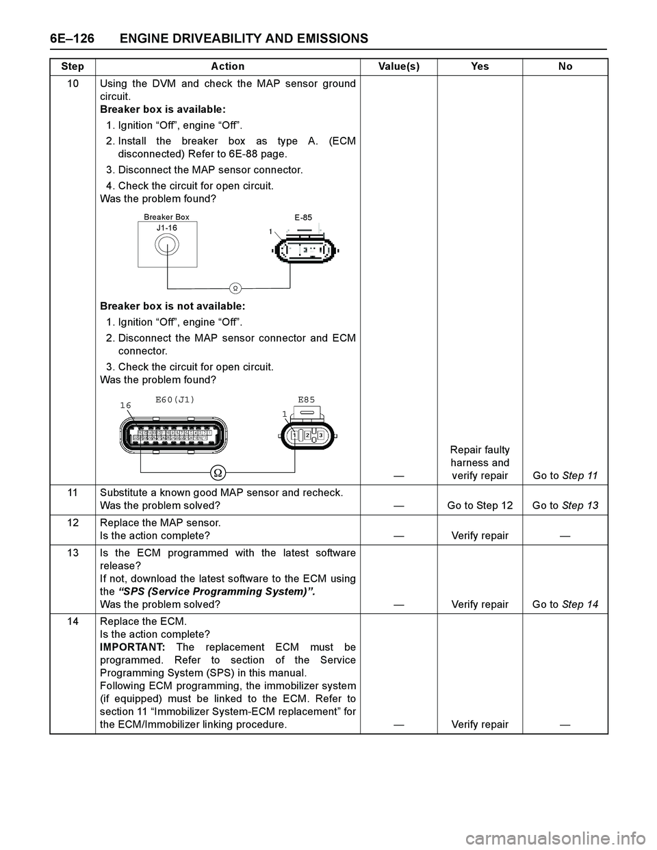
10 Using the DVM and check the MAP sensor ground
circuit.
Breaker box is available:
1. Ignition “Off”, engine “Off”.
2. Install the breaker box as type A. (ECM
disconnected) Refer to 6E-88 page.
3. Disconnect the MAP sensor connector.
4. Check the circuit for open circuit.
Was the problem found?
Breaker box is not available:
1. Ignition “Off”, engine “Off”.
2. Disconnect the MAP sensor connector and ECM
connector.
3. Check the circuit for open circuit.
Was the problem found?
—Repair faulty
harness and
verify repair Go to Step 11
11 Substitute a known good MAP sensor and recheck.
Was the problem solved?—Go to Step 12 Go to Step 13
12 Replace the MAP sensor.
Is the action complete?—Verify repair—
13 Is the ECM programmed with the latest software
release?
If not, download the latest software to the ECM using
the “SPS (Service Programming System)”.
Was the problem solved?—Verify repair Go to Step 14
14 Replace the ECM.
Is the action complete?
IMPORTANT: The replacement ECM must be
programmed. Refer to section of the Service
Programming System (SPS) in this manual.
Following ECM programming, the immobilizer system
(if equipped) must be linked to the ECM. Refer to
section 11 “Immobilizer System-ECM replacement” for
the ECM/Immobilizer linking procedure.—Verify repair— Step Action Value(s) Yes No
J1-16
Breaker Box
�
E-85
�
116E85 E60(J1)