Page 1298 of 4264
6B – 18 ENGINE COOLING
110RS005
� Check the rubber hoses for swelling.
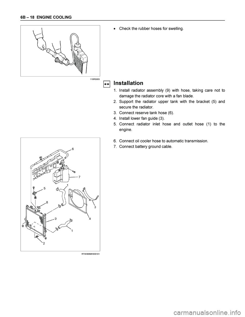
Installation
1. Install radiator assembly (9) with hose, taking care not to
damage the radiator core with a fan blade.
2. Support the radiator upper tank with the bracket (5) and
secure the radiator.
3. Connect reserve tank hose (6).
4. Install lower fan guide (3).
5. Connect radiator inlet hose and outlet hose (1) to the
engine.
RTW36BMH000101
6. Connect oil cooler hose to automatic transmission.
7. Connect battery ground cable.
Page 1299 of 4264
ENGINE COOLING 6B – 19
RTW36BSH000101
8. Pour engine coolant up to filler neck of radiator, and up to
MAX mark of reserve tank.
Important operation (in case of 100% engine coolant
change) procedure for filling with engine coolant.
Engine coolant change
Refer to 6B-8 (Draining and Refilling Cooling System).
Page 1835 of 4264
 6A-11
Symptom Possible Cause Action
Engine overheating Level of Engine Coolant too low Replenish
Fan clutch defective Replace
Thermostat defective Replace
Engi")
ENGINE MECHANICAL (6VE1 3.5L) 6A-11
Symptom Possible Cause Action
Engine overheating Level of Engine Coolant too low Replenish
Fan clutch defective Replace
Thermostat defective Replace
Engine Coolant pump defective Correct or replace
Radiator clogged Clean or replace
Radiator filler cap defective Replace
Level of oil in engine crankcase too
low or wrong engine oil Change or replenish
Resistance in exhaust system
increased Clean exhaust system or replace
defective parts
Throttle Position Sensor adjustment
incorrect Replace with Throttle Valve ASM
Throttle Position Sensor circuit open
or shorted Correct or replace
Cylinder head gasket damaged Replace
Engine overcooling Thermostat defective Replace (Use a thermostat set to
open at 82�C (180�F))
Engine lacks compression ———— Refer to Hard Start
Others Tire inflation pressure abnormal Adjust to recommended pressures
Brake drag Adjust
Clutch slipping Adjust or replace
Level of oil in engine crankcase too
high Correct level of engine oil
EGR valve defective Replace
Page 1852 of 4264

Crankshaft Pulley
Removal
1. Disconnect battery ground cable.
2. Remove air cleaner assembly.
3. Remove radiator upper fan shroud from radiator.
4. Move serp")
6A-28 ENGINE MECHANICAL (6VE1 3.5L)
Crankshaft Pulley
Removal
1. Disconnect battery ground cable.
2. Remove air cleaner assembly.
3. Remove radiator upper fan shroud from radiator.
4. Move serpentine belt tensioner to loose side using
wrench then remove serpentine belt.
850RW001
Legend
(1) Crankshaft Pulley
(2) Cooling Fan Pulley
(3) Tensioner
(4) Generator
(5) Air Conditioner Compressor
(6) Power Steering Oil Pump
(7) Serpentine Belt
5. Remove cooling fan assembly four fixing nuts,
then the cooling fan assembly.
6. Remove crankshaft pulley assembly using
5�8840�0133�0 crankshaft holder, hold crankshaf
t
pulley then remove center bolt and pulley.
Installation
1. Install crankshaft pulley using 5�8840�0133�0
crankshaft holder, hold the crankshaft pulley and
tighten center bolt to the specified torque.
Torque: 167 N�
�� �m (17.0 kg�
�� �m/123 lb ft)
2. Install cooling fan assembly and tighten bolts/nuts
to the specified torque.
Torque: 25 N�
�� �m (2.5 kg�
�� �m/18 lb ft) for fan pulley
and fan bracket.
Torque: 10 N�
�� �m (1.0 kg�
�� �m/88.5 lb in) for fan and
clutch assembly.
3. Move serpentine belt tensioner to loose side using
wrench, then install serpentine belt to normal
position.
4. Install radiator upper fan shroud.
5. Install air cleaner assembly.
Page 1853 of 4264
 6A-29
Timing Belt
Removal
1. Disconnect battery ground cable.
2. Remove air cleaner assembly.
3. Remove radiator upper fan shroud from radiator.
4. Move drive belt")
ENGINE MECHANICAL (6VE1 3.5L) 6A-29
Timing Belt
Removal
1. Disconnect battery ground cable.
2. Remove air cleaner assembly.
3. Remove radiator upper fan shroud from radiator.
4. Move drive belt tensioner to loose side using
wrench then remove drive belt.
850RW001
Legend
(1) Crankshaft Pulley
(2) Cooling Fan Pulley
(3) Tensioner
(4) Generator
(5) Air Conditioner Compressor
(6) Power Steering Oil Pump
(7) Drive Belt
5. Remove cooling fan assembly four nuts, then the
cooling fan assembly.
6. Remove cooling fan drive pulley assembly.
7. Remove idle pulley assembly.
8. Remove serpentine belt tensioner assembly.
9. Remove power steering pump assembly.
10. Remove crankshaft pulley assembly using
5�8840�0133�0 crankshaft holder, hold crankshaf
t
pulley remove center bolt, then the pulley.
11. Remove right side timing belt cover then left side
timing belt cover.
12. Remove lower timing belt cover 13. Remove pusher.
CAUTION: The pusher prevents air from entering
the oil chamber. Its rod must always be facing
upward.
014RW011
Legend
(1) Up Side
(2) Down Side
(3) Direction For Installation
(4) Locking Pin
14. Remove timing belt.
CAUTION:
1. Do not bend or twist the belt, otherwise its
core could be damaged. The belt should not be
bent at a radius less than 30 mm.
2. Do not allow oil or other chemical substances
to come in contact with the belt. They will
shorten the life.
3. Do not attempt to pry or stretch the belt with a
screw driver or any other tool during
installation.
4. Store timing belt in a cool and dark place.
Never expose the belt direct sunlight or heat.
Page 1857 of 4264
 6A-33
4. Install crankshaft pulley using 5-8840-0133-0, hold
the crankshaft pulley and tighten center bolt to the
specified torque.
Torque: 167 N�
�� �m (17.0 kg�
��")
ENGINE MECHANICAL (6VE1 3.5L) 6A-33
4. Install crankshaft pulley using 5-8840-0133-0, hold
the crankshaft pulley and tighten center bolt to the
specified torque.
Torque: 167 N�
�� �m (17.0 kg�
�� �m/123 lb ft)
5. Install fan pulley bracket and tighten fixing bolts to
the specified torque.
Torque: 25 N�
�� �m (2.5 kg�
�� �m/18 lb ft)
6. Install power steering pump assembly and tighten
to the specified torque.
Torque:
M8 bolt: 25 N�
�� �m (2.5 kg�
�� �m/18 lb ft)
M10 bolt: 43 N�
�� �m (4.4 kg�
�� �m/32 lb ft)
7. Install cooling fan assembly and tighten bolts/nuts
to the specified torque.
Torque: 25 N�
�� �m (2.5 kg�
�� �m/18 lb ft) for fan pulley
and fan bracket.
Torque: 10 N�
�� �m (1.0 kg�
�� �m/7 lb ft) for fan and
clutch assembly.
8. Move drive belt tensioner to loose side using
wrench, then install drive belt to normal position.
850RW001
Legend
(1) Crankshaft Pulley
(2) Cooling Fan Pulley
(3) Tensioner
(4) Generator
(5) Air Conditioner Compressor
(6) Power Steering Oil Pump
(7) Drive Belt
9. Install radiator upper fan shroud.
10. Install air cleaner assembly.
Page 1861 of 4264
 6A-37
Cylinder Head
Removal
1. Remove engine hood.
2. Disconnect battery ground cable.
3. Drain radiator coolant.
4. Drain engine oil.
5. Remove crankshaft pulley")
ENGINE MECHANICAL (6VE1 3.5L) 6A-37
Cylinder Head
Removal
1. Remove engine hood.
2. Disconnect battery ground cable.
3. Drain radiator coolant.
4. Drain engine oil.
5. Remove crankshaft pulley.
� Refer to removal procedure for Crankshaf
t
Pulley in this manual.
6. Remove timing belt.
� Refer to removal procedure for Timing Belt in
this manual.
7. Remove cylinder head cover LH.
� Refer to removal procedure for Cylinder Head
Cover LH in this manual.
8. Remove cylinder head cover RH.
� Refer to removal procedure for Cylinder Head
Cover RH in this manual.
9. Remove common chamber.
� Refer to removal procedure for Common
Chamber in this manual.
10. Remove cylinder head assembly.
1. Loosen eights bolts for tight cylinder head.
2. Remove cylinder head assembly.
014RW028
Legend
(1) Cylinder Head
(2) Cylinder Head Bolt
(3) Camshaft
Installation
1. Install cylinder head assembly to cylinder block.
1. Put cylinder head gasket on the cylinder block.
NOTE: There is discrimination mark “R" for righ
t
bank and “L" for left bank on the cylinder head
gasket as shown in the illustration.
Do not reuse cylinder head gasket.
011RW005
2. Align dowel pin hole to dowel pin on the
cylinder block.
3. Tighten two bolts temporarily by hand to
prevent the cylinder head assembly from
moving.
4. Using 9�8511�4209�0 cylinder head bol
t
wrench, tighten bolts in numerical order as
shown in the illustration to the specified torque.
Page 1873 of 4264
 6A-49
Engine Assembly
Removal
P1010068
1. Disconnect battery ground and positive cable.
2. Remove battery.
3. Make alignment mark on the engine hood and
h")
ENGINE MECHANICAL (6VE1 3.5L) 6A-49
Engine Assembly
Removal
P1010068
1. Disconnect battery ground and positive cable.
2. Remove battery.
3. Make alignment mark on the engine hood and
hinges before removal in order to return the hood
to original position exactly.
4. Remove engine hood.
5. Drain radiator coolant.
6. Disconnect accelerator cable and automatic cruise
control cable from throttle valve on common
chamber.
7. Remove the ECM.
� Disconnect the two connectors from the ECM.
� . Remove fixing bolts on the common chamber.
� Remove fixing bolts for ground cable.
8. Disconnect air duct with air cleaner cover.
9. Remove air cleaner assembly.
10. Disconnect canister vacuum hose.
11. Disconnect vacuum booster hose.
12. Disconnect three engine harness connectors.
13. Disconnect harness connector to transmission (lef
t
front side of engine compartment), disconnect shift
on the fly harness connector from front side o
f
front axle and remove transmission harness
bracket from engine left side.
14. Disconnect ground cable between engine and
frame.
15. Disconnect bonding cable connector on the back
of right dash panel.
16. Disconnect bonding cable terminal on the lef
t
bank.
17. Disconnect starter harness connector from starter.
18. Disconnect generator harness connector from
generator.
19. Disconnect coolant reserve tank hose from
radiator.
20. Remove radiator upper and lower hoses.
21. Remove upper fan shroud.
22. Remove cooling fan assembly four fixing nuts,
then the cooling fan assembly.
23. Move drive belt tensioner to loose side using
wrench then remove drive belt.
24. Remove power steering pump fixing bolts, then
power steering pump. Place the power steering
pump along with piping on the body side.
25. Remove air conditioning compressor fixing bolts
from bracket and place the compressor along with
piping on the body side.
26. Remove four O2 sensor harness connectors (two
each bank) from exhaust front pipe.
27. Remove three exhaust pipe fixing nuts from each
bank.
28. Remove two exhaust pipe fixing nuts from each
exhaust pipe, then move exhaust pipe to rear side
of vehicle.
29. Remove flywheel dust covers.
30. Disconnect two heater hoses from engine.
31. Disconnect fuel hose from right side o
f
transmission.
CAUTION: Plug fuel pipe on engine side and fuel
hose from fuel tank.
32. Remove transmission assembly. Refer to
Transmission section in this manual.
33. Support the engine by engine hoist.
34. Remove two left side engine mount fixing bolts
from engine mount on chassis side.
35. Remove two right side engine mount fixing bolts
from engine mount on chassis side.
36. Remove engine assembly.
Installation
CAUTION: When assembling the engine and
transmission, confirm that dowels have been
mounted in the specified positions at the engine
side. Also take care that dowel positions are
different between the manual transmission and the
automatic transmission. Otherweise, the
transmission may be damaged.