Page 1856 of 4264
6A-32 ENGINE MECHANICAL (6VE1 3.5L)
2. Install pusher and tighten bolt to the specified
torque.
Torque: 25 N�
�� �m (2.5 Kg�
�� �m/18 lb ft)
1. Install the pusher while pushing the tension
pulley to the belt.
2. Pull out pin from the pusher.
NOTE: When reusing the pusher, press the pusher with
approximately 100Kg to retract the rod, and insert a pin
(1.4 mm piano wire).
014RW011
Legend
(1) Up Side
(2) Down Side
(3) Direction for Installation
(4) Locking Pin
3. Remove double clips or equivalent clips, from
timing belt pulleys.
Turn the crankshaft pulley clockwise by two
turns.
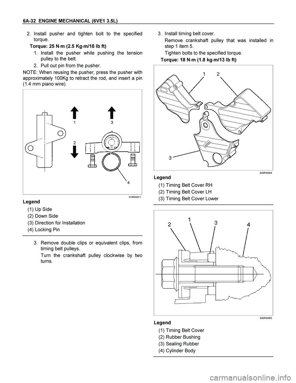
3. Install timing belt cover.
Remove crankshaft pulley that was installed in
step 1 item 5.
Tighten bolts to the specified torque.
Torque: 18 N�
�� �m (1.8 kg�
�� �m/13 lb ft)
020RW004
Legend
(1) Timing Belt Cover RH
(2) Timing Belt Cover LH
(3) Timing Belt Cover Lower
020RW003
Legend
(1) Timing Belt Cover
(2) Rubber Bushing
(3) Sealing Rubber
(4) Cylinder Body
Page 1861 of 4264
 6A-37
Cylinder Head
Removal
1. Remove engine hood.
2. Disconnect battery ground cable.
3. Drain radiator coolant.
4. Drain engine oil.
5. Remove crankshaft pulley")
ENGINE MECHANICAL (6VE1 3.5L) 6A-37
Cylinder Head
Removal
1. Remove engine hood.
2. Disconnect battery ground cable.
3. Drain radiator coolant.
4. Drain engine oil.
5. Remove crankshaft pulley.
� Refer to removal procedure for Crankshaf
t
Pulley in this manual.
6. Remove timing belt.
� Refer to removal procedure for Timing Belt in
this manual.
7. Remove cylinder head cover LH.
� Refer to removal procedure for Cylinder Head
Cover LH in this manual.
8. Remove cylinder head cover RH.
� Refer to removal procedure for Cylinder Head
Cover RH in this manual.
9. Remove common chamber.
� Refer to removal procedure for Common
Chamber in this manual.
10. Remove cylinder head assembly.
1. Loosen eights bolts for tight cylinder head.
2. Remove cylinder head assembly.
014RW028
Legend
(1) Cylinder Head
(2) Cylinder Head Bolt
(3) Camshaft
Installation
1. Install cylinder head assembly to cylinder block.
1. Put cylinder head gasket on the cylinder block.
NOTE: There is discrimination mark “R" for righ
t
bank and “L" for left bank on the cylinder head
gasket as shown in the illustration.
Do not reuse cylinder head gasket.
011RW005
2. Align dowel pin hole to dowel pin on the
cylinder block.
3. Tighten two bolts temporarily by hand to
prevent the cylinder head assembly from
moving.
4. Using 9�8511�4209�0 cylinder head bol
t
wrench, tighten bolts in numerical order as
shown in the illustration to the specified torque.
Page 1868 of 4264

1. Remove engine assembly.
� Refer to removal procedure for Engine
Assembly in this manual.
2. Remove timing belt.
� Refer to removal procedure for Timing Belt")
6A-44 ENGINE MECHANICAL (6VE1 3.5L)
1. Remove engine assembly.
� Refer to removal procedure for Engine
Assembly in this manual.
2. Remove timing belt.
� Refer to removal procedure for Timing Belt in
this manual.
3. Remove oil pan and crankcase.
� Refer to removal procedure for Oil Pan and
Crankcase in this manual.
4. Remove oil pipe with O-ring.
5. Remove oil strainer assembly with O-ring.
6. Remove oil pump assembly.
� Refer to removal procedure for Oil Pump in this
manual.
7. Remove cylinder body side bolts.
8. Remove oil gallery.
9. Remove flywheel.
10. Remove rear oil seal retainer.
� Refer to removal procedure for Rear Oil Seal in
this manual.
11. Remove connecting rod caps.
12. Remove crankshaft main bearing caps.
13. Remove crankshaft and main bearings.
Installation
1. Install crankshaft and main bearings.
� Install main bearing in the cylinder block and
main bearing cap respectively.
Apply new engine oil to upper and lower main
bearings.
NOTE:
� Do not apply engine oil to the bearing back faces.
� Make sure that main bearings are in correc
t
position.
� Install crankshaft with care.
� Apply engine oil to the thrust washer.
� Install thrust washer on No.3 journal.
� Oil grooves in thrust washer must face the
crankshaft.
015RS012
015RS013
2. Install crankshaft main bearing caps.
�
Apply engine oil to the thread and seating
surface of each bearing cap fixing bolt.
NOTE:
� Do not apply engine oil to the bearing back faces.
� Install bearing caps in the order of numbers,
starting with cylinder block front side.
� Tighten main bearing fixing bolts to the specified
torque.
Torque: 39 N�
�� �m (4.0 kg�
�� �m/29 lb ft)
�
After tightening the bolts, make sure that the
crankshaft rotates smoothly.
3. Install connecting rod caps.
� The cap number must be same as connecting
rod number.
�
Apply engine oil to the thread and seating
surface of each nut.
Page 1869 of 4264
 6A-45
� Tighten nuts to the specified torque.
Torque: 54 N�
�� �m (5.5 kg�
�� �m/40 lb ft)
�
After tightening the nuts, make sure that the
crankshaft rotates smoothl")
ENGINE MECHANICAL (6VE1 3.5L) 6A-45
� Tighten nuts to the specified torque.
Torque: 54 N�
�� �m (5.5 kg�
�� �m/40 lb ft)
�
After tightening the nuts, make sure that the
crankshaft rotates smoothly.
4. Install rear oil seal retainer.
� Remove oil on cylinder block and retainer fitting
surface.
�
Apply sealant (TB1207B or equivalent) to
retainer fitting surface as shown in illustration.
� The oil seal retainer must be installed within 5
minutes after sealant application to preven
t
premature hardening of sealant.
015RW002
Legend
(1) Around Bolt Holes
(2) Around Dowel Pin
� Apply engine oil to oil seal lip and align a dowel
pin hole in the cylinder block with that in the
retainer.
� Tighten retainer fixing bolts to the specified
torque.
Torque: 18 N�
�� �m (1.8 kg�
�� �m/13 lb ft)
015RW001
5. Install flywheel.
� Clean tapped holes in the crankshaft.
� Remove oil on crankshaft and flywheel fitting
surface.
NOTE:
� Do not reuse the bolts.
� Do not apply oil or thread lock to the bolts.
� Tighten fixing bolts to the specified torque.
Torque: 54 N�
�� �m (5.5 kg�
�� �m/40 lb ft)
015RS018
Page 1870 of 4264

6. Install oil gallery.
� Clean contact surface of oil gallery and main
bearing cap.
Apply engine oil to oil gallery fixing bolts and
tighten the bolts in two")
6A-46 ENGINE MECHANICAL (6VE1 3.5L)
6. Install oil gallery.
� Clean contact surface of oil gallery and main
bearing cap.
Apply engine oil to oil gallery fixing bolts and
tighten the bolts in two steps, in the orde
r
shown.
Torque:
1st step: 29 N�
�� �m (3.0 kg�
�� �m/21 lb ft)
2nd step: 55�
�� ��
�� �65�
�� �
7. Install cylinder body side bolts and tighten bolts in
order to the specified torque.
Torque: 39 N�
�� �m (4.0 kg�
�� �m/29 lb ft)
NOTE: Do not apply the oil to the bolts.
012RS007
8. Install oil pump assembly.
� Remove oil on cylinder block and oil pump
mounting surface.
� Apply sealant (TB1207B or equivalent) to the oil
pump mounting surface.
� The oil pump assembly must be installed within
5 minutes after sealant application to preven
t
premature hardening of sealant.
� Apply engine oil to oil seal lip.
� Install oil pump in the cylinder block and tighten
fixing bolts to the specified torque.
Torque: 25 N�
�� �m (2.5 kg�
�� �m/18 lb ft)
051RW002
Legend
(1) Around Bolt Holes
(2) Around Dowel Pin
051RW001
9. Install oil strainer with O-ring, tighten to the
specified torque.
Torque: 25 N�
�� �m (2.5 kg�
�� �m/18 lb ft)
10. Install oil pipe with O-ring, tighten fixing bolts to the
specified torque.
Torque: 25 N�
�� �m (2.5 kg�
�� �m/18 lb ft)
Page 1872 of 4264

Rear Oil Seal
Removal
1. Remove transmission assembly.
� See Transmission section in this manual.
2. Remove flywheel.
3. Remove rear oil seal using a seal re")
6A-48 ENGINE MECHANICAL (6VE1 3.5L)
Rear Oil Seal
Removal
1. Remove transmission assembly.
� See Transmission section in this manual.
2. Remove flywheel.
3. Remove rear oil seal using a seal remover.
NOTE: Take care not to damage the crankshaft or oil
seal retainer when removing oil seal.
Installation
1. Apply engine oil to oil seal lip and install oil seal
using 5�8840�2286�0.
015RS017
2. Install flywheel.
� Clean tapped holes in the crankshaft.
� Remove oil on the crankshaft and flywheel
mounting surface.
� Tighten fixing bolts to the specified torque.
NOTE: Do not reuse the bolts and do not apply oil o
r
thread lock to the bolts.
Torque: 54 N�
�� �m (5.5 kg�
�� �m/40 lb ft)
015RS018
3. Install transmission.
� See Transmission section in this manual.
CAUTION: When assembling the engine and
transmission, confirm that dowels have been
mounted in the specified positions at the engine
side. Take care that dowel positions are different
between the manual transmission and the
automatic transmission. Otherwise, the
transmission may be damaged.
012RS009
Page 1875 of 4264
 6A-51
19. Reconnect ground cable between engine and
chassis.
20. Reconnect harness connector to transmission and
install transmission harness bracket on engine lef
t
s")
ENGINE MECHANICAL (6VE1 3.5L) 6A-51
19. Reconnect ground cable between engine and
chassis.
20. Reconnect harness connector to transmission and
install transmission harness bracket on engine lef
t
side.
21. Reconnect three engine harness connectors.
22. Reconnect vacuum booster hose.
23. Reconnect canister vacuum hose.
24. Install air cleaner assembly.
25. Reconnect air duct.
26. Reconnect accelerator cable to throttle valve on
common chamber.
27. Install the ECM.
� Tighten the four bolts.
Torque : 10 N�
�� �m (1.0 kg�
�� �m/7 lb ft)
�Connect the two connectors.
�Tighten the two ground cable bolts.
28. Install engine hood to the origine position.
� Refer to installation procedure for Body section
in this manual.
� Install accelerator control cable to accelerato
r
cable bracket.
� Rotate the ratchet ring in direction an arrow 90�
� Confirm marking of outer cap must be uppe
r
side.
� Slider the lock in direction B.
� Confirm ratchet ring is locked.
RTW46ASH000201
Legend
(1) Cable Bracket
(2) Ratchet ring
(3) Outer Cap
(4) Lock
(5) Paint Mark
(6) Arrow Mark
29. Install the cable clips to accelerator control cable.
Page 1886 of 4264

5. Install lower valve spring seat, valve spring and
upper valve spring seat then put split collars on the
upper spring seat, using the 5�8840�2446�0 valve
sprin")
6A-62 ENGINE MECHANICAL (6VE1 3.5L)
5. Install lower valve spring seat, valve spring and
upper valve spring seat then put split collars on the
upper spring seat, using the 5�8840�2446�0 valve
spring compresor and 5�8840�2547�0 valve
spring compressor adapter to install the spli
t
collars.
014RW042
6. Install tappet with shim.
7. Install camshaft assembly.
� Refer to installation procedure for Camshaft in
this manual.
Valve Clearance Adjustments
NOTE: To adjust valve clearance, apply engine oil to
the cam as well as to the adjusting shim (2) with the
cylinder head built on the cylinder block, give a fe
w
turns to the camshaft by means of timing pulley
tightening bolt, and measure valve clearance when the
nose of cam is just opposite to maximum cam lift (1) as
shown in illustration below.
014RW081
Legend
(1) Cam
(2) Shim
(3) Tappet
Valve Clearance Standard Value (cold)
Intake: 0.23 mm�
�� �0.33 mm
(0.0091 in�
�� �0.0130 in)
Exhaust: 0.25 mm�
�� �0.35 mm
(0.0098 in�
�� �0.0138 in)
Selection of Adjusting Shim
Shim to be selected = (Thickness of removed
shim) + (Valve clearance measurement �Standard
value) Based on the above formula, the best suited
shim should be selected from 41 sorts of shim
(differently thick at 0.02mm (0.0008 in) intervals from
2.40mm (0.0945 in) through 3.2mm (0.1260 in) thick).
Install the shim and check valve clearance.