Page 1801 of 4264
EXHAUST SYSTEM 6F – 7
GENERAL DESCRIPTION
This system controls the formation of NOx emission by recirculating the exhaust gas into the combustion chamber
through the intake manifold.
4JA1T(L):
The two EGR valves are controlled by two Vacuum Switching Valve (VSV) controlled by EGR controller according to
signals from various sensors.
The amount of EGR depends on the number of engine rotations and the opening of the accelerator.
RTW46ELF001201
Page 1805 of 4264
EXHAUST SYSTEM 6F – 11
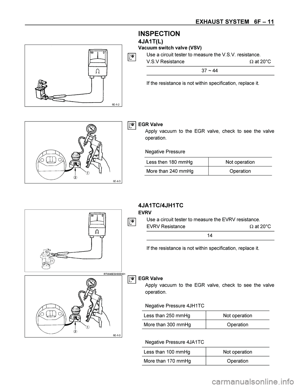
INSPECTION
4JA1T(L)
Vacuum switch valve (VSV)
Use a circuit tester to measure the V.S.V. resistance.
V.S.V Resistance � at 20°C
37 ~ 44
If the resistance is not within specification, replace it.
EGR Valve
Apply vacuum to the EGR valve, check to see the valve
operation.
Negative Pressure
4JA1TC/4JH1TC
RTW46ESH000301
EVRV
Use a circuit tester to measure the EVRV resistance.
EVRV Resistance � at 20°C
14
If the resistance is not within specification, replace it.
EGR Valve
Apply vacuum to the EGR valve, check to see the valve
operation.
Negative Pressure 4JH1TC
Less than 250 mmHg Not operation
More than 300 mmHg Operation
Negative Pressure 4JA1TC
Less than 100 mmHg Not operation
More than 170 mmHg Operation
Less then 180 mmHg Not operation
More than 240 mmHg Operation
Page 1828 of 4264

Engine Diagnosis
Hard Starting
1. Starting Motor Does Not Turn Over
Troubleshooting Procedure
Turn on headlights and starter switch.
Symptom Possible Cau")
6A-4 ENGINE MECHANICAL (6VE1 3.5L)
Engine Diagnosis
Hard Starting
1. Starting Motor Does Not Turn Over
Troubleshooting Procedure
Turn on headlights and starter switch.
Symptom Possible Cause Action
Headlights go out or dim considerably Battery run down or under charged Recharge or replace battery
Terminals poorly connected Clean battery posts and terminals
and connect properly
Starting motor coil circuit shorted Overhaul or replace
Starting motor defective Overhaul or replace
2. Ignition Trouble �
�� � Starting Motor Turns Over But
Engine Does Not Start Spark Test
Disconnect an ignition coil from any spark plug.
Connect the spark plug tester 5�8840�0383�0, start the
engine, and check if a spark is generated in the spark
plug tester. Before starting the engine, make sure that
the spark plug tester is properly grounded. To avoid
electrical shock, do not touch the part where insulation
of the ignition coil is broken while the engine is running.
Symptom Possible Cause Action
Spark jumps across gap Spark plug defective Clean or replace
Ignition timing incorrect Refer to Ignition System
Fuel not reaching fuel injector(s) or
engine Refer to item 3 (Trouble in fuel
system)
Valve timing incorrect Adjust
Engine lacks compression Refer to item 4 (Engine lacks
compression)
No sparking takes place Ignition coil disconnected or broken Connect properly or replace
Electronic Ignition System with
module Replace
Poor connections in engine harness Correct
Engine Control Module cable
disconnected or defective Correct or replace
Page 1952 of 4264
6C-10 ENGINE FUEL (6VE1 3.5L)
Fuel Pump Relay
General Description
In order to control the fuel pump and sender assembly
(FPAS) operation, the FPAS relay is provided. When
the starter switch is turned to “ON" position, the FPAS
relay operates the FPAS for 2 seconds.
When it is turned to “START" position, the Engine
Control Module receives the reference pulse from the
Ignition Control Module and it operates the relay, again
causing the FPAS to feed fuel.
Page 1974 of 4264
6D3-2 STARTING AND CHARGING SYSTEM (6VE1 3.5L)
Starting System
General Description
Cranking Circuit
The cranking system consists of a battery, starter,
starter switch, starter relay, etc. These main
components are connected.
Starter
The cranking system employs a magnetic type
reduction starter in which the motor shaft is also used
as a pinion shaft. When the starter switch is turned on,
the contacts of magnetic switch are closed, and the
armature rotates. At the same time, the plunger is
attracted, and the pinion is pushed forward by the shif
t
lever to mesh with the ring gear.
Then, the ring gear runs to start the engine. When the
engine starts and the starter switch is turned off, the
plunger returns, the pinion is disengaged from the ring
gear, and the armature stops rotation. When the engine
speed is higher than the pinion, the pinion idles, so tha
t
the armature is not driven.
Page 1976 of 4264
6D3-4 STARTING AND CHARGING SYSTEM (6VE1 3.5L)
Diagnosis
Symptom Possible Cause Action
Starter does not run Charging failure Repair charging system
Battery Failure Replace Battery
Terminal connection failure Repair or replace terminal connector
and/or wiring harness
Starter switch failure Repair or replace starter switch
Starter failure Repair or replace starter
Page 1978 of 4264
6D3-6 STARTING AND CHARGING SYSTEM (6VE1 3.5L)
Disassembled View
065R100012
Legend (7) Housing
(1) Lead Wire (8) Over Running Clutch
(2) Through Bolt (9) Return Spring
(3) Yoke Assembly (10) Steel Ball
(4) Yoke Cover (11) Idle Pinion
(5) Brush and Brush Holder (12) Retainer
(6) Armature (13) Magnetic Switch
Page 1979 of 4264
STARTING AND CHARGING SYSTEM (6VE1 3.5L) 6D3-7
Disassembly
1. Remove the lead wire (1) from the magnetic switch.
2. Remove the through bolts (2).
065RY00053
Legend
(1) Lead Wire
(2) Through Bolt
3. Remove the yoke from the magnetic.
4. Remove the yoke cover.
5. Use the long nose pliers to remove the brush and
brush holder.
065RY00054
065RY00055
Legend
(1) Spring
(2) Brush
6. Remove the armature.
7. Remove the housing.
8. Remove the overrunning clutch from the housing.
065RY00056


Fuel Pump Relay
General Description
In order to control the fuel pump and sender assembly
(FPAS) operation, the FPAS relay is provided. When
the starter switch is tur")

Starting System
General Description
Cranking Circuit
The cranking system consists of a battery, starter,
starter switch, starter relay, etc. These m")

Diagnosis
Symptom Possible Cause Action
Starter does not run Charging failure Repair charging system
Battery Failure Replace Battery
Terminal")

Disassembled View
065R100012
Legend (7) Housing
(1) Lead Wire (8) Over Running Clutch
(2) Through Bolt (9) Return Spring
(3) Yoke Assem")
 6D3-7
Disassembly
1. Remove the lead wire (1) from the magnetic switch.
2. Remove the through bolts (2).
065RY00053
Legend
(1) Lead Wire
(2) T")