Page 1980 of 4264
6D3-8 STARTING AND CHARGING SYSTEM (6VE1 3.5L)
9. Remove the return spring from the magnetic switch.
065R100014
10. Remove the steel ball from the overrunning clutch.
065RY00058
11.Remove the idle pinion from the magnetic switch.
065R100015
12. Remove the retainer from the magnetic switch.
065R100016
13. Remove the magnetic switch.
Page 1983 of 4264
 6D3-11
Brush Spring
Use spring balancer to measure the spring setting force
when remove the spring from the brush.
Standard: 17.65–23.54 N (38.9–51.9")
STARTING AND CHARGING SYSTEM (6VE1 3.5L) 6D3-11
Brush Spring
Use spring balancer to measure the spring setting force
when remove the spring from the brush.
Standard: 17.65–23.54 N (38.9–51.9 lb)
Limit: 11.77 N (25.9 lb)
Magnetic Switch
Temporarilly connect the magnetic switch between the
overrunning clutch and housing.
Perform the steps described below in 3 to 5 seconds.
1. Pull in test
Connect the ground (-) to terminal C and magnetic
switch body.
Verify that the pinion pulls out when the battery (+)
pole is connected to terminal 50.
065R100017
2. Hold in test
Observe that the pinion stays when the lead wire is
disconnected from terminal C.
065R100018
3. Return test
Connect the ground (-) to terminal 50 and magnetic
switch body.
Verify that the pinion pulls out when the battery (+)
pole is connected to terminal C and the pinion
pulls away when the lead wire is disconnected from
terminal 50.
065R100019
Field Coil
1. Check for continuity between the end of the field coil
and yoke body.
Replace the field coil, if there is continuity.
065RY00065
Page 1987 of 4264
 6D3-15
Charging System
General Description
The IC integral regulator charging system and its main
components are connected as shown in illustration.
The")
STARTING AND CHARGING SYSTEM (6VE1 3.5L) 6D3-15
Charging System
General Description
The IC integral regulator charging system and its main
components are connected as shown in illustration.
The regulator is a solid state type and it is mounted
along with the brush holder assembly inside the
generator installed on the rear end cover.
The generator does not require particular maintenance
such as voltage adjustment.
The rectifier connected to the stator coil has eigh
t
diodes to transform AC voltage into DC voltage.
This DC voltage is connected to the output terminal o
f
generator.
General On–Vehicle Inspection
The operating condition of charging system is indicated
by the charge warning lamp. The warning lamp comes
on when the starter switch is turned to “ON" position.
The charging system operates normally if the lamp
goes off when the engine starts.
If the warning lamp shows abnormality or i
f
undercharged or overcharged battery condition is
suspected, perform diagnosis by checking the charging
system as follows:
1. Check visually the belt and wiring connector.
2. With the engine stopped, turn the stator switch to
“ON" position and observe the warning lamp.
If lamp does not come on:
Disconnect wiring connector from generator, and
ground the terminal “L" on connector side.
If lamp comes on:
Repair or replace the generator.
F06RW009
Page 1988 of 4264

Generator
Removal
1. Disconnect battery ground cable.
2. Move drive belt tensioner to loose side using
wrench then remove drive belt (1).
3. Di")
6D3-16 STARTING AND CHARGING SYSTEM (6VE1 3.5L)
Generator
Removal
1. Disconnect battery ground cable.
2. Move drive belt tensioner to loose side using
wrench then remove drive belt (1).
3. Disconnect the wire from terminal “B" and
disconnect the connector (4).
4. Remove generator fixing bolt (3).
5. Remove generator assembly (2).
060RW002
Inspection
1. Disconnect the wiring connector from generator.
2. With the engine stopped, turn starter switch to “ON"
and connect a voltmeter between connecto
r
terminal L (2) and ground or between terminal IG (1)
and ground.
066RW001
If voltage is not present, the line between battery
and connector is disconnected and so requires
repair.
3. Reconnect the wiring connector to the generator,
run the engine at middle speed, and turn off all
electrical devices other than engine.
4. Measure battery voltage. If it exceeds 16V, repair o
r
replace the generator.
5. Connect an ammeter to output terminal o
f
generator, and measure output current under load
by turning on the other electrical devices (eg.,
headlights). At this time, the voltage must not be
less than 13V.
Installation
1. Install generator assembly to the position to be
installed.
2. Install generator assembly and tighten the fixing
bolts to the specified torque.
Torque:
M10 bolt: 52 N�
�� �m (5.3 kg�
�� �m/38 lb ft)
M8 bolt: 25 N�
�� �m (2.5 kg�
�� �m/18 lb ft)
3. Connect wiring harness connector and direc
t
terminal “B".
4. Move drive belt tensioner to loose side using
wrench, then install drive belt to normal position.
5. Reconnect battery ground cable.
Page 2001 of 4264
3.5L ENGINE DRIVEABILITY AND EMISSIONS 6E-5
ABBREVIATION CHARTS
Abbreviations Appellation
A/C Air conditioner
A/T Automatic transmission
ACC Accessory
BLK Black
BLU Blue
BRN Brown
CAN Controller Area Network
CEL Check engine lamp
CKP Crankshaft position
CMP Camshaft position
DLC Data link connector
DTC Diagnosis trouble code
DVM Digital voltage meter
ECM Engine control module
ECT Engine coolant temperature
EEPROM Electrically erasable & programmable read only memory
EGR Exhaust gas recalculation
GND Ground
GRY Gray
HO2S Heated Oxygen Sensor
IAT Intake air temperature
IAC Idle air control
IG Ignition
M/T Manual transmission
MAF Mass air flow
MIL Malfunction indicator lamp
OBD On-board diagnostic
ORN Orange
PNK Pink
PROM Programmable read only memory
RED Red
SW Switch
TPS Throttle position sensor
TCM Transmission control module
VCC Voltage Constant Control
VIO Violet
VSS Vehicle speed sensor
WHT White
WOT Wide open throttle
YEL Yellow
Page 2005 of 4264
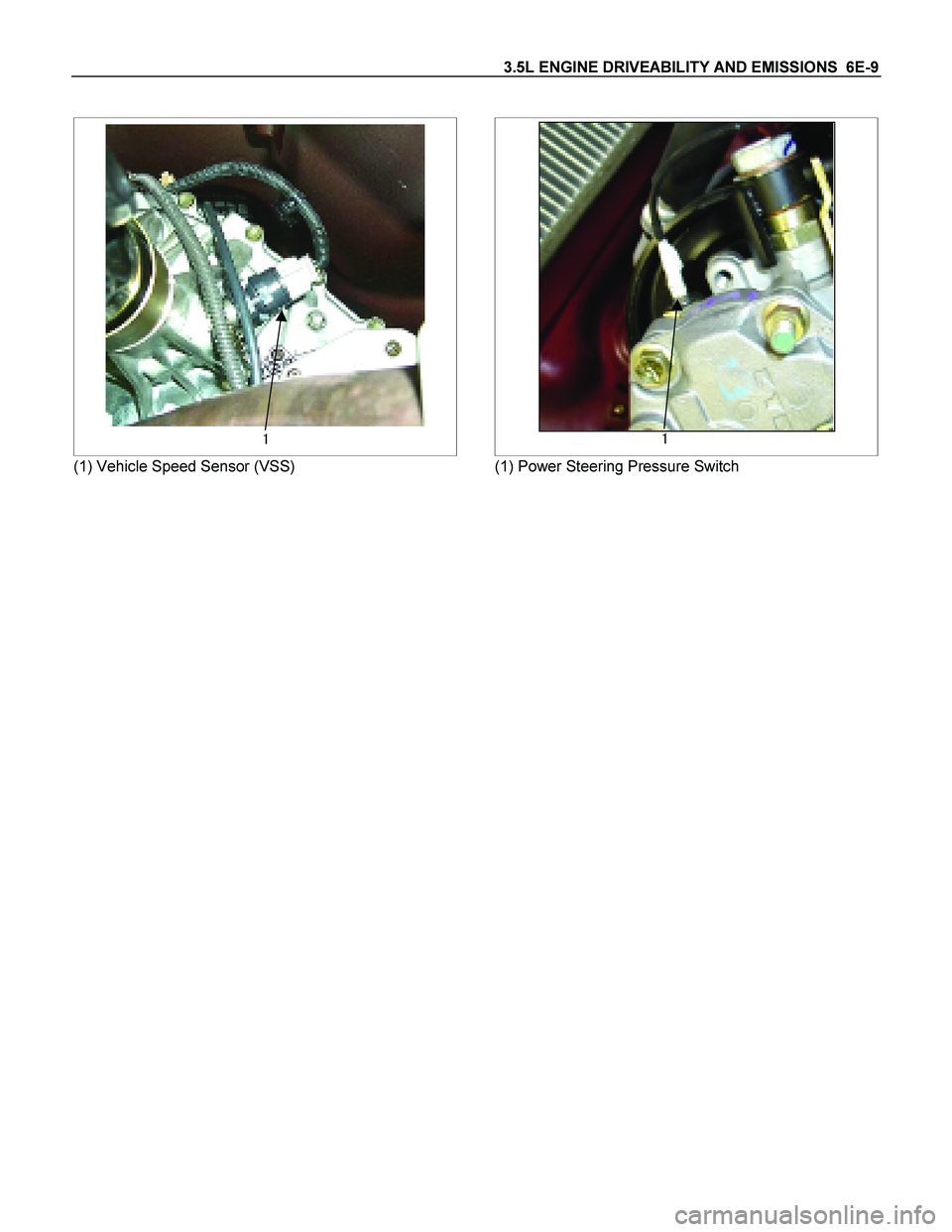
3.5L ENGINE DRIVEABILITY AND EMISSIONS 6E-9
�
(1) Vehicle Speed Sensor (VSS)
�
(1) Power Steering Pressure Switch
Page 2023 of 4264
3.5L ENGINE DRIVEABILITY AND EMISSIONS 6E-27
CONNECTOR LIST
No. Connector face No. Connector face
B-24
Green
Meter-B C-108
WhiteJ/B E1
B-56
White
J/B I4 C-109
SilverBody-LH ; ground
B-58
Black
Check connector E-2
Magnetic clutch
B-62
White
Ignition switch (IGSUB : G1) E-6
Fuel injector
B-63
White
Ignition switch (IGSUB : G2) E-7
Fuel injector
B-68
Immobilizer E-8
Fuel injector
C-2
Silver
Engine room-RH ground E-9
Fuel injector
C-24
Triple pressure switch E-51
Fuel injector
C-94
Gray TCM-(A) E-52
Fuel injector
C-107
White
J/B E2 E-53
Ignition coil
Page 2024 of 4264
6E-28 3.5L ENGINE DRIVEABILITY AND EMISSIONS
No. Connector face No. Connector face
E-54
Ignition coil E-64
Oil pressure switch (P/STRG)
E-55
Ignition coil E-66
Duty solenoid
E-56
Ignition coil E-68
Throttle position sensor
E-57
Ignition coil E-69
Temperature sensor
E-58
Ignition coil E-70
IACV
E-59
Crank position sensor E-72
Engine earth-A
E-60
ECM-A E-73
Engine earth-A
E-61
ECM-B E-74
Engine earth-B
E-62
Cam position sensor E-76
EGR valve
E-63
MAF sensor E-77
O2 sensor RH-Front

9. Remove the return spring from the magnetic switch.
065R100014
10. Remove the steel ball from the overrunning clutch.
065RY00058
11")


E-55
Ignition coil E-66
Duty solenoid
E-")