Page 1872 of 4264
6A-48 ENGINE MECHANICAL (6VE1 3.5L)
Rear Oil Seal
Removal
1. Remove transmission assembly.
� See Transmission section in this manual.
2. Remove flywheel.
3. Remove rear oil seal using a seal remover.
NOTE: Take care not to damage the crankshaft or oil
seal retainer when removing oil seal.
Installation
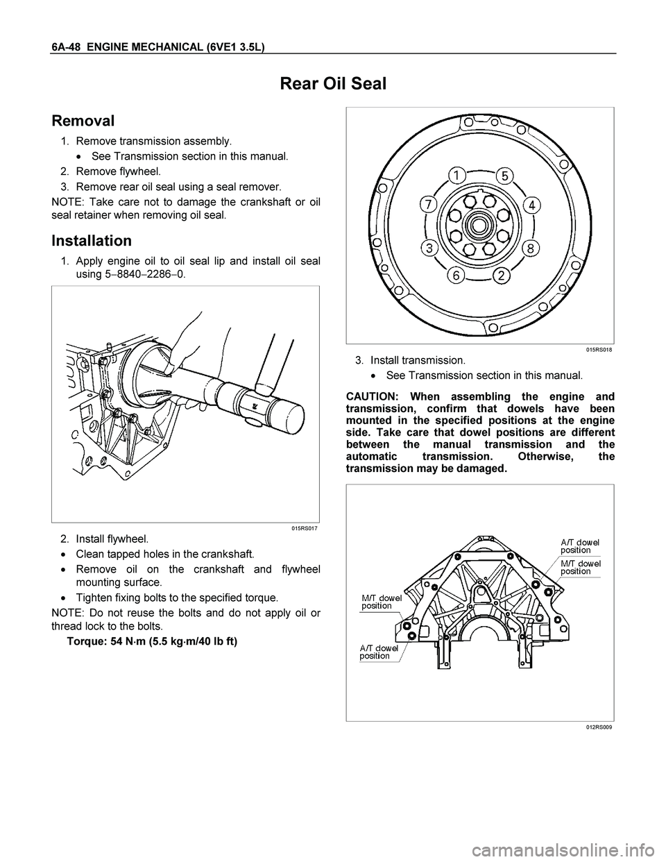
1. Apply engine oil to oil seal lip and install oil seal
using 5�8840�2286�0.
015RS017
2. Install flywheel.
� Clean tapped holes in the crankshaft.
� Remove oil on the crankshaft and flywheel
mounting surface.
� Tighten fixing bolts to the specified torque.
NOTE: Do not reuse the bolts and do not apply oil o
r
thread lock to the bolts.
Torque: 54 N�
�� �m (5.5 kg�
�� �m/40 lb ft)
015RS018
3. Install transmission.
� See Transmission section in this manual.
CAUTION: When assembling the engine and
transmission, confirm that dowels have been
mounted in the specified positions at the engine
side. Take care that dowel positions are different
between the manual transmission and the
automatic transmission. Otherwise, the
transmission may be damaged.
012RS009
Page 1874 of 4264
6A-50 ENGINE MECHANICAL (6VE1 3.5L)
012RS009
1. Install engine assembly. Tighten engine mount
fixing bolts to frame to the specified torque.
Torque: 41 N�
�� �m (4.2 kg�
�� �m/30 lb ft)
2. Reconnect fuel hose to fuel pipe on engine.
3. Install transmission assembly. Refer to
Transmission section in this manual.
4. Reconnect two heater hoses to engine.
5. Install flywheel dust covers.
6. Install exhaust pipe and temporally tighten two
(each bank) rear exhaust flange nuts then tighten
three stud nuts (each bank) between exhaus
t
manifold and exhaust pipe, finally tighten rear side
stud nuts to the specified torque.
Torque: 67 N�
�� �m (6.8 kg�
�� �m/49 lb ft)
LTW36FSH000101
7. Reconnect O2 sensor connector.
8. Install cooling fan assembly and tighten bolts/nuts
to the specified torque.
Torque: 25 N�
�� �m (2.5 kg�
�� �m/18 lb ft) for fan pulley
and fan bracket.
Torque : 10 N�
�� �m (1.0 kg�
�� �m/7 lb ft) for fan and
clutch assembly.
9. Install air conditioner compressor to engine and
tighten to the specified torque.
Torque : 43 N�
�� �m (4.4 kg�
�� �m/32 lb ft)
10. Install power steering pump, tighten fixing bolt to
the specified torque.
Torque :
M8 bolts : 25 N�
�� �m (2.5 kg�
�� �m/18 lb ft)
M10 bolts : 43 N�
�� �m (4.4 kg�
�� �m/32 lb ft)
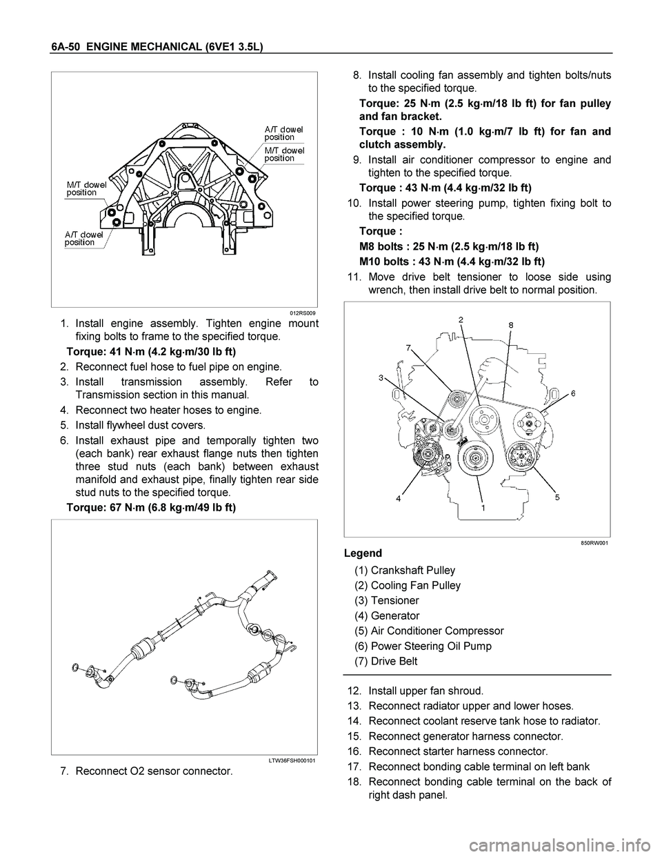
11. Move drive belt tensioner to loose side using
wrench, then install drive belt to normal position.
850RW001
Legend
(1) Crankshaft Pulley
(2) Cooling Fan Pulley
(3) Tensioner
(4) Generator
(5) Air Conditioner Compressor
(6) Power Steering Oil Pump
(7) Drive Belt
12. Install upper fan shroud.
13. Reconnect radiator upper and lower hoses.
14. Reconnect coolant reserve tank hose to radiator.
15. Reconnect generator harness connector.
16. Reconnect starter harness connector.
17. Reconnect bonding cable terminal on left bank
18. Reconnect bonding cable terminal on the back o
f
right dash panel.
Page 1878 of 4264
6A-54 ENGINE MECHANICAL (6VE1 3.5L)
5. Water jacket sealing plugs seating surfaces.
Reassembly
1. Install spark plug and tighten all the spark plugs to
specified torque.
Torque: 18 Nm (1.8 kgm/13 lb ft)
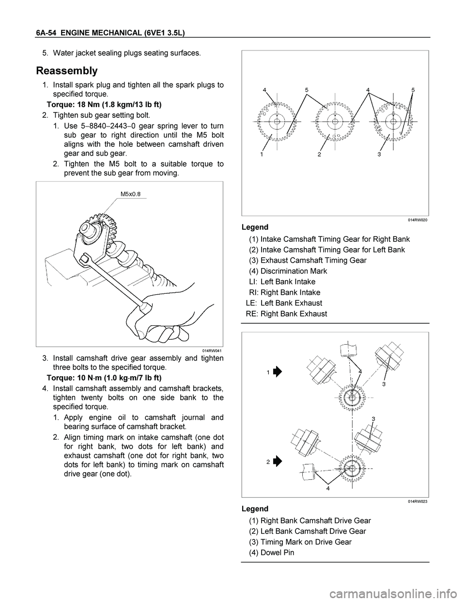
2. Tighten sub gear setting bolt.
1. Use 5�8840�2443�0 gear spring lever to turn
sub gear to right direction until the M5 bol
t
aligns with the hole between camshaft driven
gear and sub gear.
2. Tighten the M5 bolt to a suitable torque to
prevent the sub gear from moving.
014RW041
3. Install camshaft drive gear assembly and tighten
three bolts to the specified torque.
Torque: 10 N�
�� �m (1.0 kg�
�� �m/7 lb ft)
4. Install camshaft assembly and camshaft brackets,
tighten twenty bolts on one side bank to the
specified torque.
1. Apply engine oil to camshaft journal and
bearing surface of camshaft bracket.
2.
Align timing mark on intake camshaft (one dot
for right bank, two dots for left bank) and
exhaust camshaft (one dot for right bank, two
dots for left bank) to timing mark on camshaf
t
drive gear (one dot).
014RW020
Legend
(1) Intake Camshaft Timing Gear for Right Bank
(2) Intake Camshaft Timing Gear for Left Bank
(3) Exhaust Camshaft Timing Gear
(4) Discrimination Mark
LI: Left Bank Intake
RI: Right Bank Intake
LE: Left Bank Exhaust
RE: Right Bank Exhaust
014RW023
Legend
(1) Right Bank Camshaft Drive Gear
(2) Left Bank Camshaft Drive Gear
(3) Timing Mark on Drive Gear
(4) Dowel Pin
Page 1880 of 4264
6A-56 ENGINE MECHANICAL (6VE1 3.5L)
Valve Spring, Oil Controller, Valve, Valve Guide
Valve Spring, Oil Controller, Valve, Valve Guide and Associated Parts
014RW039
Legend
(1) Camshaft Bracket Fixing Bolts
(2) Camshaft Assembly Inlet
(3) Camshaft Assembly Exhaust
(4) Shim
(5) Tappet
(6) Split Collar
(7) Spring Upper Seat
(8) Valve Spring
(9) Oil Controller
(10) Spring Lower Seat
(11) Valve Guide
(12) Valve
Page 1881 of 4264
ENGINE MECHANICAL (6VE1 3.5L) 6A-57
Disassembly
1. Remove camshaft bracket fixing bolts (1).
2. Remove camshaft assembly (intake).
3. Remove camshaft assembly (Exhaust side).
4. Remove shim (4) and tappet (5).
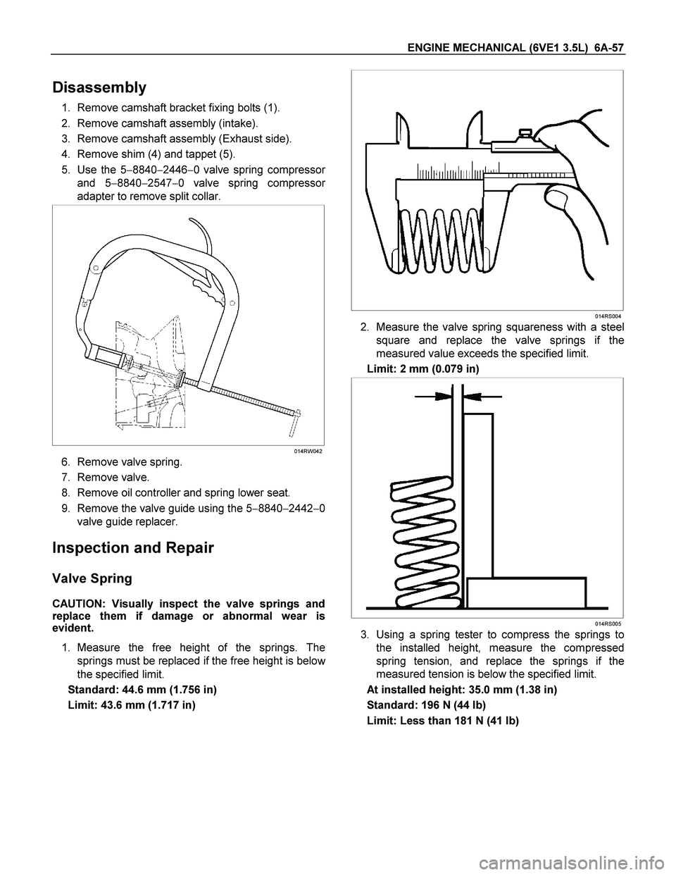
5. Use the 5�8840�2446�0 valve spring compresso
r
and 5�8840�2547�0 valve spring compressor
adapter to remove split collar.
014RW042
6. Remove valve spring.
7. Remove valve.
8. Remove oil controller and spring lower seat.
9. Remove the valve guide using the 5�8840�2442�0
valve guide replacer.
Inspection and Repair
Valve Spring
CAUTION: Visually inspect the valve springs and
replace them if damage or abnormal wear is
evident.
1. Measure the free height of the springs. The
springs must be replaced if the free height is belo
w
the specified limit.
Standard: 44.6 mm (1.756 in)
Limit: 43.6 mm (1.717 in)
014RS004
2. Measure the valve spring squareness with a steel
square and replace the valve springs if the
measured value exceeds the specified limit.
Limit: 2 mm (0.079 in)
014RS005
3. Using a spring tester to compress the springs to
the installed height, measure the compressed
spring tension, and replace the springs if the
measured tension is below the specified limit.
At installed height: 35.0 mm (1.38 in)
Standard: 196 N (44 lb)
Limit: Less than 181 N (41 lb)
Page 1883 of 4264
ENGINE MECHANICAL (6VE1 3.5L) 6A-59
Valve Guide Replacement
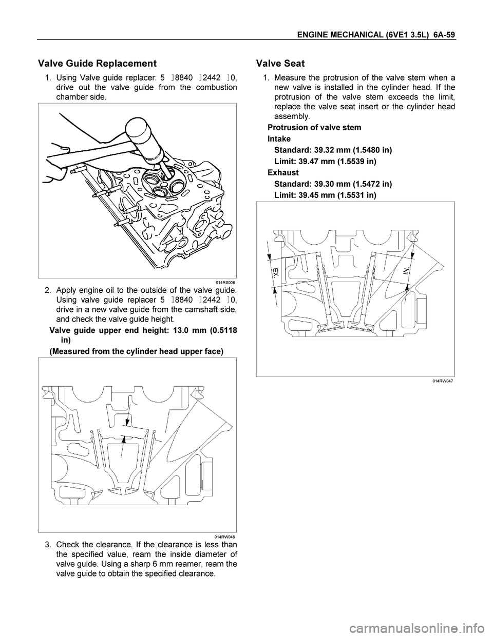
1. Using Valve guide replacer: 5�8840�2442�0,
drive out the valve guide from the combustion
chamber side.
014RS008
2. Apply engine oil to the outside of the valve guide.
Using valve guide replacer 5�8840�2442�0,
drive in a new valve guide from the camshaft side,
and check the valve guide height.
Valve guide upper end height: 13.0 mm (0.5118
in)
(Measured from the cylinder head upper face)
014RW046
3. Check the clearance. If the clearance is less than
the specified value, ream the inside diameter o
f
valve guide. Using a sharp 6 mm reamer, ream the
valve guide to obtain the specified clearance.
Valve Seat
1. Measure the protrusion of the valve stem when a
new valve is installed in the cylinder head. If the
protrusion of the valve stem exceeds the limit,
replace the valve seat insert or the cylinder head
assembly.
Protrusion of valve stem
Intake
Standard: 39.32 mm (1.5480 in)
Limit: 39.47 mm (1.5539 in)
Exhaust
Standard: 39.30 mm (1.5472 in)
Limit: 39.45 mm (1.5531 in)
014RW047
Page 1885 of 4264
ENGINE MECHANICAL (6VE1 3.5L) 6A-61
Valve Seat Insert Replacement
1. Arc weld the rod at several points. Be careful not
to damage the aluminum section.
2.
Allow the rod to cool for a few minutes. This will
cause the valve seat to shrink.
3. Strike the rod and pull it out.
014RS015
4. Carefully clean the valve seat press�fit section on
the cylinder head side.
5. Heat the press�fit section with steam or some
other means to cause expansion. Cool the valve
seat with dry ice or some other means.
6. Insert the press�fit section into the valve sea
t
horizontally.
Standard fitting interference: 0.14 mm�
�� �0.09 mm
(0.0055 in�
�� �0.0035 in)
7.
After insertion, use a seat grinder to grind finish
the seating face. Carefully note the seating angle,
the contact width, and the depression.
8. Lap the valve and the seat.
Reassembly
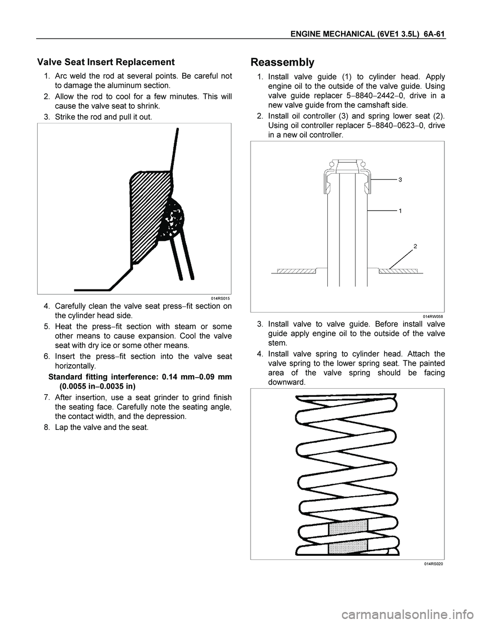
1. Install valve guide (1) to cylinder head. Apply
engine oil to the outside of the valve guide. Using
valve guide replacer 5�8840�2442�0, drive in a
new valve guide from the camshaft side.
2. Install oil controller (3) and spring lower seat (2).
Using oil controller replacer 5�8840�0623�0, drive
in a new oil controller.
014RW058
3. Install valve to valve guide. Before install valve
guide apply engine oil to the outside of the valve
stem.
4. Install valve spring to cylinder head. Attach the
valve spring to the lower spring seat. The painted
area of the valve spring should be facing
downward.
014RS020
Page 1886 of 4264
6A-62 ENGINE MECHANICAL (6VE1 3.5L)
5. Install lower valve spring seat, valve spring and
upper valve spring seat then put split collars on the
upper spring seat, using the 5�8840�2446�0 valve
spring compresor and 5�8840�2547�0 valve
spring compressor adapter to install the spli
t
collars.
014RW042
6. Install tappet with shim.
7. Install camshaft assembly.
� Refer to installation procedure for Camshaft in
this manual.
Valve Clearance Adjustments
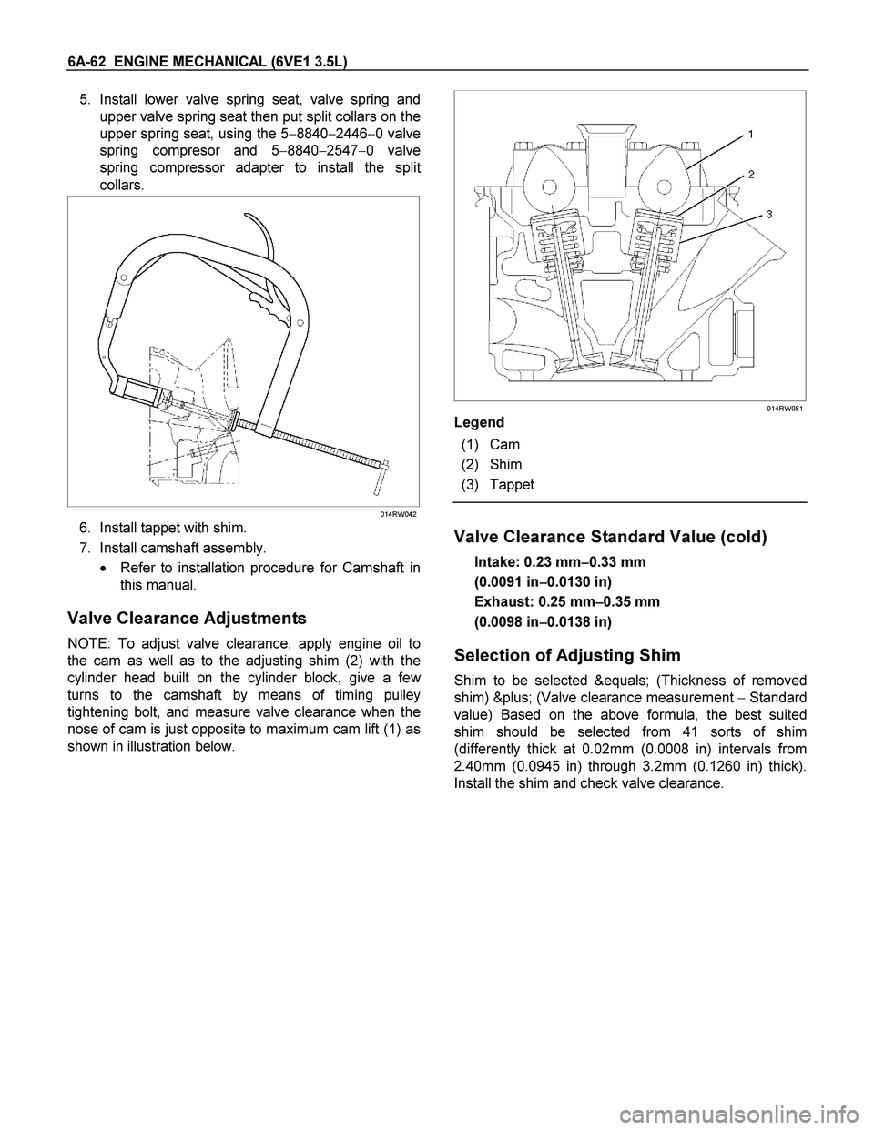
NOTE: To adjust valve clearance, apply engine oil to
the cam as well as to the adjusting shim (2) with the
cylinder head built on the cylinder block, give a fe
w
turns to the camshaft by means of timing pulley
tightening bolt, and measure valve clearance when the
nose of cam is just opposite to maximum cam lift (1) as
shown in illustration below.
014RW081
Legend
(1) Cam
(2) Shim
(3) Tappet
Valve Clearance Standard Value (cold)
Intake: 0.23 mm�
�� �0.33 mm
(0.0091 in�
�� �0.0130 in)
Exhaust: 0.25 mm�
�� �0.35 mm
(0.0098 in�
�� �0.0138 in)
Selection of Adjusting Shim
Shim to be selected = (Thickness of removed
shim) + (Valve clearance measurement �Standard
value) Based on the above formula, the best suited
shim should be selected from 41 sorts of shim
(differently thick at 0.02mm (0.0008 in) intervals from
2.40mm (0.0945 in) through 3.2mm (0.1260 in) thick).
Install the shim and check valve clearance.