Page 3516 of 4264
3C-24 FRONT SUSPENSION
Upper Ball Joint
Upper Ball Joint and Associated Parts
RTW340LF001101
Legend
(1)
Bolt
(2)
Upper Ball Joint
(3)
Nut
(4)
Nut and Cotter Pin
(5)
Nut
Removal
1. Raise the vehicle and support the frame with
suitable safety stands.
2. Remove wheel and tire assembly. Refer to wheel
in this section.
3. Remove nut (5).
4. Remove upper ball joint nut and cotter pin, then
use remover 5-8840-2017-0 to remove the uppe
r
ball joint from the knuckle.
CAUTION: Be careful not to damage the ball joint
boot and brake hose.
Page 3529 of 4264
FRONT SUSPENSION 3C-37
Knuckle
Knuckle and Associated Parts
RTW340LF001301
Legend
(1) Torsion Bar
(2 )Lower Ball Joint, Nut and Cotter Pin
(3) Back Plate
(4) Knuckle Assembly
(5) Knuckle
(6) Needle Bearing (4�4 Model Only)
(7) Thrust Washer (4�4 Model Only)
(8) Oil Seal (4�
4 Model Only)
(9) Upper Ball Joint, Nut and Cotter Pin
(10) Speed Sensor harness
Removal
1. Raise the vehicle and support the frame with
suitable safety stands.
2. Remove wheel and tire assembly. Refer to Wheel
in this section.
3. Remove the brake caliper. Refer to Disc Brakes in
Brake section.
Page 3532 of 4264
3C-40 FRONT SUSPENSION
Upper Control Arm
Upper Control Arm and Associated Parts
RTW440LF001301
Legend
(1)Bolt and Plate
(2)Camber Shims
(3)Caster Shims
(4)Nut Assembly
(5)Upper Control Arm Assembly
(6)Fulcrum Pin
(7)Bushing
(8)Plate
(9)Nut
(10)Speed Sensor harness
(11)Nut and Cotter Pin
(12)Upper Ball Joint, Bolt and Nut
Removal
1. Raise the vehicle and support the frame with
suitable safety stands.
2. Remove wheel and tire assembly. Refer to Wheel
in this section.
3. Remove the brake caliper and disconnect brake
pipe. Refer to Disc Brakes in Brake section.
Page 3547 of 4264
FRONT SUSPENSION 3C-55
2. VEHICLE PULLS TO RIGHT OR LEFT
Checkpoint Trouble Cause Countermeasure
Steering linkage, and upper
and lower link
Rubber bushing for upper and
lower link
Wheel alignment
Vehicle trim height
Replace
Replace
Adjust
Adjust
Deformed
Worn
Incorrect
Incorrect
Brake adjustment (binding)
Adjust
Replace
Incorrect
Collapsed or break (4�
2
Except high ride suspension)
Collapsed or twisted (4�
4, 4�
2
High ride suspension)
Continued on the next pageOK OK OK OK
NG NG NG NG NG NG
OK OK Coil spring (4�2 Except high
ride suspension)
Torsion bar (4�
4, 4�
2 High
ride suspension)
Front wheel bearing
Adjust or replace
Incorrect adjustment or
abrasion
NG
Page 3555 of 4264
FRONT SUSPENSION 3C-63
8. EXCESSIVELY OR PARTIALLY WORN TIRE
Checkpoint Trouble Cause Countermeasure
Brake adjustment
Wheel alignment
Adjust
Adjust
Incorrect
Incorrect
Front wheel bearingReplace
Adjust
Faulty
Improper
OK
NG NG NG NG
OK OKTire pressure
Tire rotationRotate tires at recomended
intervalsNot rotated OK
NG
Page 3561 of 4264
REAR SUSPENSION 3D-5
LEAF SPRING AND SHOCK ABSORBER
LEAF SPRING AND ASSOCIATED PARTS
460R300001
Legend
1. Parking Brake Cable Bracket
2. Nut and Washer
3. Nut and Washer
4. Shock Absorber
5. Nut
6. U Bolt and Seat
7. Lower Clamp
8. Nut
9. Shackle Plate
10. Shackle Pin
11. Rubber Bushing
12. Nut and Plain Washer
13. Spring Pin
14. Leaf Spring
15. Bump Rubber
Page 3562 of 4264

3D-6 REAR SUSPENSION
F03L100003
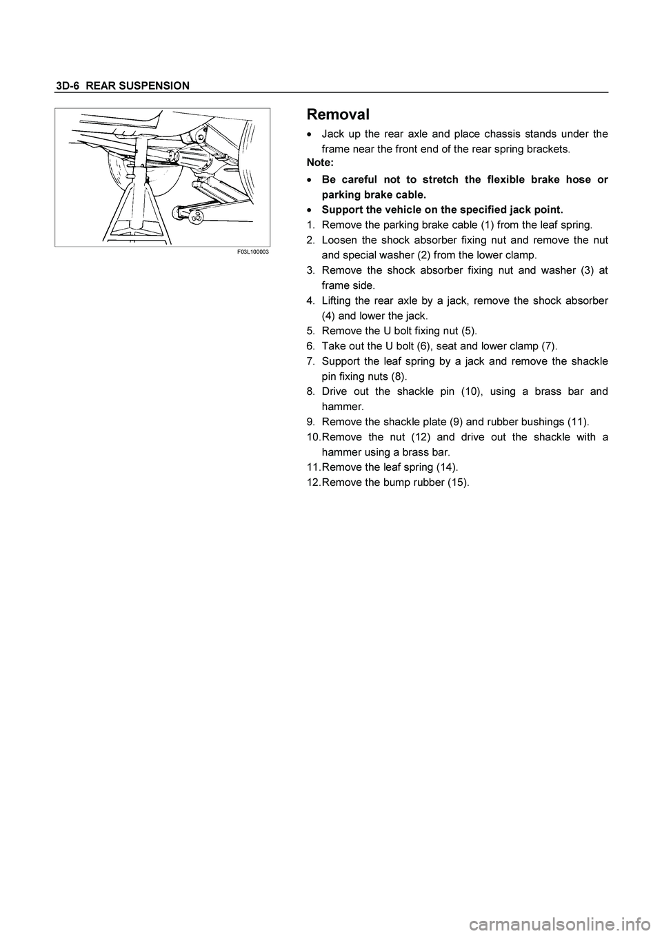
Removal
� Jack up the rear axle and place chassis stands under the
frame near the front end of the rear spring brackets.
Note:
� Be careful not to stretch the flexible brake hose o
r
parking brake cable.
� Support the vehicle on the specified jack point.
1. Remove the parking brake cable (1) from the leaf spring.
2. Loosen the shock absorber fixing nut and remove the nu
t
and special washer (2) from the lower clamp.
3. Remove the shock absorber fixing nut and washer (3) at
frame side.
4. Lifting the rear axle by a jack, remove the shock absorbe
r
(4) and lower the jack.
5. Remove the U bolt fixing nut (5).
6. Take out the U bolt (6), seat and lower clamp (7).
7. Support the leaf spring by a jack and remove the shackle
pin fixing nuts (8).
8. Drive out the shackle pin (10), using a brass bar and
hammer.
9. Remove the shackle plate (9) and rubber bushings (11).
10. Remove the nut (12) and drive out the shackle with a
hammer using a brass bar.
11. Remove the leaf spring (14).
12. Remove the bump rubber (15).
Page 3564 of 4264

3D-8 REAR SUSPENSION
Installation
1. Install the bump rubber (15) and bolt and tighten it to the
specified torque.
Torque N�m (kg�m/lb�ft)
42 (4.3/31)
2. Install the leaf spring (14).
� The leaf spring assembly should be installed so that the
built-in rubber bush is toward the front.
� Align the holes of the spring eye and frame bracket.
� Insert the spring pin (13) toward vehicle inner side
through the frame bracket holes and the spring bush
hole.
� Tighten the nut (12) a little and after the vehicle is
lowered, tighten it to the specified torque.
Torque N
�m (kg
�m/lb
�ft)
152 (15.5/112)
RTW340LF000101
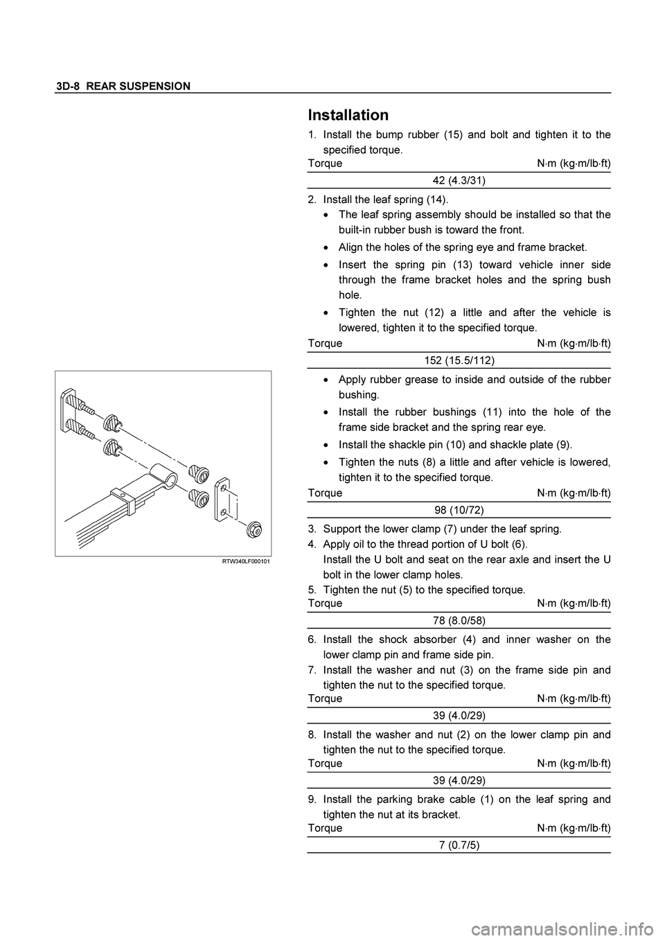
� Apply rubber grease to inside and outside of the rubber
bushing.
� Install the rubber bushings (11) into the hole of the
frame side bracket and the spring rear eye.
� Install the shackle pin (10) and shackle plate (9).
� Tighten the nuts (8) a little and after vehicle is lowered,
tighten it to the specified torque.
Torque N�m (kg�m/lb�ft)
98 (10/72)
3. Support the lower clamp (7) under the leaf spring.
4. Apply oil to the thread portion of U bolt (6).
Install the U bolt and seat on the rear axle and insert the U
bolt in the lower clamp holes.
5. Tighten the nut (5) to the specified torque.
Torque N�m (kg�m/lb�ft)
78 (8.0/58)
6. Install the shock absorber (4) and inner washer on the
lower clamp pin and frame side pin.
7. Install the washer and nut (3) on the frame side pin and
tighten the nut to the specified torque.
Torque N�m (kg�m/lb�ft)
39 (4.0/29)
8. Install the washer and nut (2) on the lower clamp pin and
tighten the nut to the specified torque.
Torque N�m (kg�m/lb�ft)
39 (4.0/29)
9. Install the parking brake cable (1) on the leaf spring and
tighten the nut at its bracket.
Torque N
�m (kg
�m/lb
�ft)
7 (0.7/5)