Page 1834 of 4264

Engine Lacks Power
Symptom Possible Cause Action
Trouble in fuel system Fuel Pressure Control Valve not
working normally Replace
Fuel injector clogged Clea")
6A-10 ENGINE MECHANICAL (6VE1 3.5L)
Engine Lacks Power
Symptom Possible Cause Action
Trouble in fuel system Fuel Pressure Control Valve not
working normally Replace
Fuel injector clogged Clean or replace
Fuel pipe clogged Clean
Fuel filter clogged or fouled Replace
Fuel pump drive circuit not working
normally Correct or replace
Fuel tank not sufficiently breathing
due to clogged Evaporative Emission
Control System circuit Clean or replace
Water in fuel system Clean
Inferior quality fuel in fuel system Use fuel of specified octane rating
Engine Control Module supplied poor
voltage Correct circuit
Throttle Position Sensor cable broken
or poor connections Correct or replace
Throttle Position Sensor defective Replace
Mass Airflow Sensor not working
normally Replace
Manifold Absolute Pressure Sensor
not working normally Replace
Intake Air Temperature Sensor not
working normally Replace
Engine Coolant Temperature Sensor
circuit open or shorted Correct or replace
Engine Coolant Temperature Sensor
defective Replace
Engine Control Module defective Replace
Trouble in intake or exhaust system Air Cleaner Filter clogged Replace filter element
Air duct kinked or flattened Correct or replace
Exhaust system clogged Correct or replace
Ignition failure ———— Refer to Hard Start Troubleshooting
Guide
Heat range of spark plug inadequateInstall spark plugs of adequate heat
range
Ignition coil defective Replace
Page 1835 of 4264
 6A-11
Symptom Possible Cause Action
Engine overheating Level of Engine Coolant too low Replenish
Fan clutch defective Replace
Thermostat defective Replace
Engi")
ENGINE MECHANICAL (6VE1 3.5L) 6A-11
Symptom Possible Cause Action
Engine overheating Level of Engine Coolant too low Replenish
Fan clutch defective Replace
Thermostat defective Replace
Engine Coolant pump defective Correct or replace
Radiator clogged Clean or replace
Radiator filler cap defective Replace
Level of oil in engine crankcase too
low or wrong engine oil Change or replenish
Resistance in exhaust system
increased Clean exhaust system or replace
defective parts
Throttle Position Sensor adjustment
incorrect Replace with Throttle Valve ASM
Throttle Position Sensor circuit open
or shorted Correct or replace
Cylinder head gasket damaged Replace
Engine overcooling Thermostat defective Replace (Use a thermostat set to
open at 82�C (180�F))
Engine lacks compression ———— Refer to Hard Start
Others Tire inflation pressure abnormal Adjust to recommended pressures
Brake drag Adjust
Clutch slipping Adjust or replace
Level of oil in engine crankcase too
high Correct level of engine oil
EGR valve defective Replace
Page 1839 of 4264
 6A-15
Abnormal Combustion
Symptom Possible Cause Action
Trouble in fuel system Fuel pressure control valve defectiveReplace
Fuel filter clogged Replace
Fuel pum")
ENGINE MECHANICAL (6VE1 3.5L) 6A-15
Abnormal Combustion
Symptom Possible Cause Action
Trouble in fuel system Fuel pressure control valve defectiveReplace
Fuel filter clogged Replace
Fuel pump clogged Clean or replace
Fuel tank or fuel pipe clogged Clean or replace
Fuel injector clogged Clean or replace
Fuel pump relay defective Replace
Power supply cable for fuel pump
broken or poor connections Reconnect, correct or replace
Mass Airflow (MAF) Sensor circuit
open or defective Correct or replace
MAF Sensor defective Replace
Engine Coolant Temperature (ECT)
Sensor circuit open or shorted Correct or replace
ECT Sensor defective Replace
Throttle Position Sensor adjustment
incorrect Readjust
Throttle Position Sensor defective Replace
Throttle Position Sensor connector
poor connections Reconnect
Vehicle Speed Sensor cable poor
connections or defective Correct or replace
Vehicle Speed Sensor loosely fixed Fix tightly
Vehicle Speed Sensor in wrong
contact or defective Replace
Engine Control Module cable poor
connections or defective Correct or replace
Page 1840 of 4264
6A-16 ENGINE MECHANICAL (6VE1 3.5L)
Symptom Possible Cause Action
Trouble in emission control system Heated Oxygen Sensor circuit open Correct or replace
Heated Oxygen Sensor defective Replace
Signal vacuum hose loosely fitted or
defective Correct or replace
EGR Valve circuit open or shorted Correct or replace
EGR Valve defective Replace
ECT Sensor circuit open or shorted Correct or replace
Canister Purge Valve circuit open or
shorted Correct or replace
Canister Purge Valve defective Replace
ECT Sensor defective Replace
Positive Crankcase Ventilation (PCV)
valve and hose clogged Correct or replace
Evaporator system Refer to Section 6E
Trouble in ignition system ———— Refer to “Engine Lacks Power"
Trouble in cylinder head parts Carbon deposits in combustion
chamber Remove carbon
Carbon deposit on valve, valve seat
and valve guide Remove carbon
Page 1844 of 4264

Malfunction Indicator Lamp
The instrument panel “CHECK ENGINE\" Malfunction
Indicator Lamp (MIL) illuminates by self diagnostic
system when the system checks th")
6A-20 ENGINE MECHANICAL (6VE1 3.5L)
Malfunction Indicator Lamp
The instrument panel “CHECK ENGINE" Malfunction
Indicator Lamp (MIL) illuminates by self diagnostic
system when the system checks the starting of engine,
or senses malfunctions. ”CHECK ENGINE" MIL does
not illuminate at the starting of engine
Symptom Possible Cause Action
“CHECK ENGINE" MIL does not
illuminate at the starting of engine Bulb defective Replace
MIL circuit open Correct or replace
Command signal circuit to operate
self diagnostic system shorted Correct or replace
Engine Control Module (ECM) cable
loosely connected, disconnected or
defective Correct or replace
ECM defective Replace
“CHECK ENGINE" MIL illuminates,
and stays on Deterioration of heated oxygen
sensor internal element Replace
Heated oxygen sensor connector
terminal improper contact Reconnect properly
Heated oxygen sensor lead wire
shorted Correct
Heated oxygen sensor circuit open Correct or replace
Deterioration of engine coolant
temperature sensor internal element Replace
Engine coolant temperature sensor
connector terminal improper contact Reconnect properly
Engine coolant temperature sensor
lead wire shorted Correct
Engine coolant temperature sensor
circuit open Correct or replace
Throttle position sensor open or
shorted circuits Correct or replace
Deterioration of crankshaft position
sensor Replace
Crankshaft position sensor circuit
open or shorted Correct or replace
Vehicle speed sensor circuit open Correct or replace
Intake air temperature sensor circuit
open or shorted Correct or replace
Fuel injector circuit open or shorted Correct or replace
ECM driver transistor defective Replace ECM
Malfunctioning of ECM RAM
(Random Access Memory) or ROM
(Read Only Memory) Replace ECM
Page 1845 of 4264
 6A-21
Cylinder Head Cover LH
Removal
1. Disconnect battery ground cable.
2. Disconnect positive crankcase ventilation hose.
3. Remove camshaft angle sensor connecto")
ENGINE MECHANICAL (6VE1 3.5L) 6A-21
Cylinder Head Cover LH
Removal
1. Disconnect battery ground cable.
2. Disconnect positive crankcase ventilation hose.
3. Remove camshaft angle sensor connector.
4. Remove ground cable fixing bolt on cylinder head
cover.
5. Ignition coil connector and ignition coil.
� Disconnect the three connectors from the
ignition coils.
� Remove harness bracket bolt on cylinder head
cover.
� Remove fixing bolts on ignition coils.
060RW078
Legend
(1) Ignition Coil Connector
(2) Bolt
(3) Ignition Coil Assemblies
6. Remove fixing bolt for fuel injector harness
bracket.
7. Remove eight fixing bolts, then the cylinder head
cover.
010RW001
Installation
1. Install cylinder head cover.
� Clean the sealing surface of cylinder head and
cylinder head cover to remove oil and sealing
materials completely.
� Apply sealant (TB-1207B or equivalent) of bead
diameter 2-3 mm at eight place of arched area
of camshaft bracket on front and rear sides.
� The cylinder head cover must be installed with
in 5 minutes after sealant application to preven
t
hardening of sealant.
� Tighten bolts to the specified torque.
Torque : 9 N�
�� �m (0.9 kg�
�� �m/7 lb ft)
010RW006
Page 1846 of 4264
6A-22 ENGINE MECHANICAL (6VE1 3.5L)
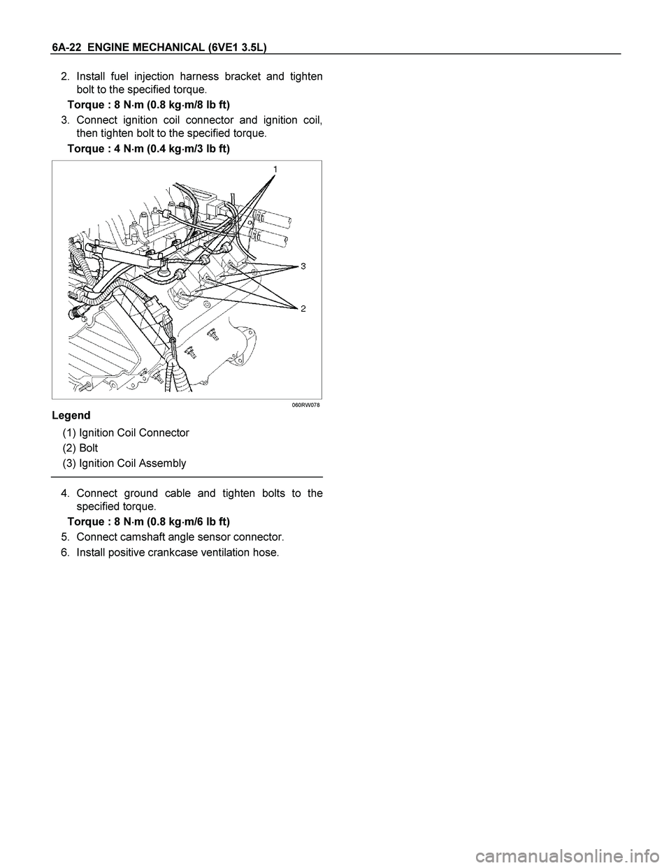
2. Install fuel injection harness bracket and tighten
bolt to the specified torque.
Torque : 8 N�
�� �m (0.8 kg�
�� �m/8 lb ft)
3. Connect ignition coil connector and ignition coil,
then tighten bolt to the specified torque.
Torque : 4 N�
�� �m (0.4 kg�
�� �m/3 lb ft)
060RW078
Legend
(1) Ignition Coil Connector
(2) Bolt
(3) Ignition Coil Assembly
4. Connect ground cable and tighten bolts to the
specified torque.
Torque : 8 N�
�� �m (0.8 kg�
�� �m/6 lb ft)
5. Connect camshaft angle sensor connector.
6. Install positive crankcase ventilation hose.
Page 1848 of 4264

Common Chamber
Removal
1. Disconnect battery ground cable.
2. Remove air cleaner duct assembly.
3. Remove the ECM.
� Disconnect the two connectors from the E")
6A-24 ENGINE MECHANICAL (6VE1 3.5L)
Common Chamber
Removal
1. Disconnect battery ground cable.
2. Remove air cleaner duct assembly.
3. Remove the ECM.
� Disconnect the two connectors from the ECM.
� Remove fixing bolts on the common chamber.
� Remove fixing bolts for ground cable.
060RW025
4. Remove the accelerator control cable from
accelerator control cable bracket.
� Slide the lock in direction A
� Rotate the ratchet ring in indirection an arro
w
90�
RTW46ASH000201
Legend
(1) Cable Bracket
(2) Ratchet ring
(3) Outer Cap
(4) Lock
(5) Paint Mark
(6) Arrow Mark
5. Remove the accelerator control cable from the
throttle.
6. Disconnect vacuum booster hose from common
chamber.
7. Disconnect connector from manifold absolute
pressure sensor, idle air control valve, throttle
position sensor, solenoid valve, electric vacuum
sensing valve.
8. Disconnect vacuum hose on canister VSV and
positive crankcase ventilation hose, fuel rail
assembly with pressure control valve bracket.
9. Remove ventilation hose from throttle valve and
intake duct and remove water hose.
10. Remove exhaust gas recirculation valve assembly
fixing bolt and nut on common chamber.
11. Remove two bolts from common chamber rea
r
side for remove fuel hose bracket.
12. Remove common chamber four bolts and fou
r
nuts then remove the common chamber.
025RW001
Legend
(1) Common Chamber
(2) Throttle Valve Assembly
(3) Bolt
13. Remove the four throttle body fixing bolts.

Symptom Possible Cause Action
Trouble in emission control system Heated Oxygen Sensor circuit open Correct or replace
Heated Oxygen Sensor defective Replace")