Page 1786 of 4264
6E–414 4JA1/4JH1 ENGINE DRIVEABILITY AND EMISSIONS
10 Remove the MAF & IAT sensor assembly and check
for the following conditions.
Objects blocking at the MAF sensor element.
If a problem is found, repair as necessary.
Was the problem found?—Verify repair Go to Step 11
11 Check the MAF sensor harness for the following
conditions.
Check for poor connector connection.
Check for misrouted harness.
Check for any accessory parts which may cause
electric interference.
If a problem is found, repair as necessary.
Was a problem found? —Verify repair Go to Step 12
12 Substitute a known good MAF & IAT sensor assembly
and recheck.
Was the problem solved?—Go to Step 13Go to Step 21
13 Replace the MAF & IAT sensor assembly.
Is the action complete?—Veri fy repai r—
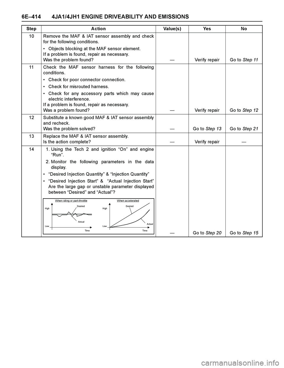
14 1. Using the Tech 2 and ignition “On” and engine
“Run”.
2. Monitor the following parameters in the data
display.
“Desired Injection Quantity” & “Injection Quantity”
“Desired Injection Start” & “Actual Injection Start”
Are the large gap or unstable parameter displayed
between “Desired” and “Actual”?
—Go to Step 20Go to Step 15 Step Action Value(s) Yes No
When idling or part-throttle When accelerated
HighD esired
Low
Ti m e Actu al
High
LowD esired
Actual
Tim e
Page 1791 of 4264
4JA1/4JH1 ENGINE DRIVEABILITY AND EMISSIONS 6E–419
CRANKSHAFT POSITION (CKP)
SENSOR
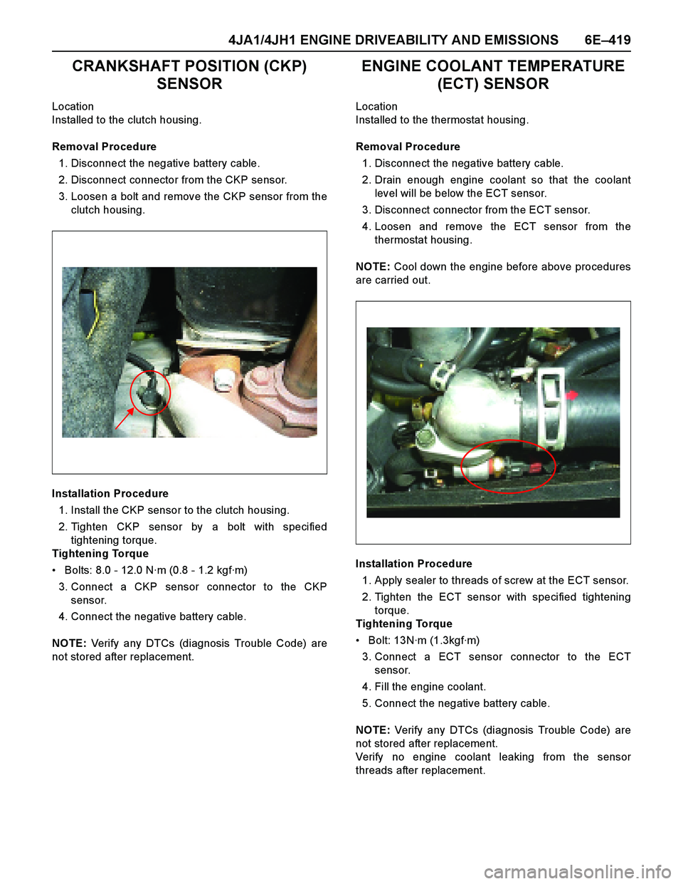
Location
Installed to the clutch housing.
Removal Procedure
1. Disconnect the negative battery cable.
2. Disconnect connector from the CKP sensor.
3. Loosen a bolt and remove the CKP sensor from the
clutch housing.
Installation Procedure
1. Install the CKP sensor to the clutch housing.
2. Tighten CKP sensor by a bolt with specified
tightening torque.
Tightening Torque
Bolts: 8.0 - 12.0 N·m (0.8 - 1.2 kgf·m)
3. Connect a CKP sensor connector to the CKP
sensor.
4. Connect the negative battery cable.
NOTE: Verify any DTCs (diagnosis Trouble Code) are
not stored after replacement.
ENGINE COOLANT TEMPERATURE
(ECT) SENSOR
Location
Installed to the thermostat housing.
Removal Procedure
1. Disconnect the negative battery cable.
2. Drain enough engine coolant so that the coolant
level will be below the ECT sensor.
3. Disconnect connector from the ECT sensor.
4. Loosen and remove the ECT sensor from the
thermostat housing.
NOTE: Cool down the engine before above procedures
are carried out.
Installation Procedure
1. Apply sealer to threads of screw at the ECT sensor.
2. Tighten the ECT sensor with specified tightening
torque.
Tightening Torque
Bolt: 13N·m (1.3kgf·m)
3. Connect a ECT sensor connector to the ECT
sensor.
4. Fill the engine coolant.
5. Connect the negative battery cable.
NOTE: Verify any DTCs (diagnosis Trouble Code) are
not stored after replacement.
Verify no engine coolant leaking from the sensor
threads after replacement.
Page 1792 of 4264
6E–420 4JA1/4JH1 ENGINE DRIVEABILITY AND EMISSIONS
MASS AIR FLOW (MAF) & INTAKE
AIR TEMPERATURE (IAT) SENSOR
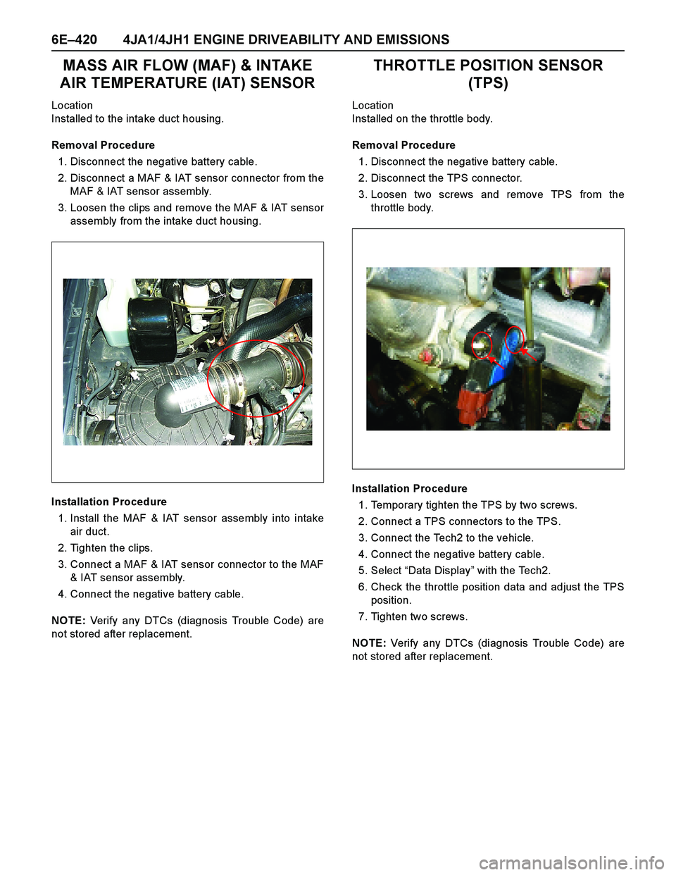
Location
Installed to the intake duct housing.
Removal Procedure
1. Disconnect the negative battery cable.
2. Disconnect a MAF & IAT sensor connector from the
MAF & IAT sensor assembly.
3. Loosen the clips and remove the MAF & IAT sensor
assembly from the intake duct housing.
Installation Procedure
1. Install the MAF & IAT sensor assembly into intake
air duct.
2. Tighten the clips.
3. Connect a MAF & IAT sensor connector to the MAF
& IAT sensor assembly.
4. Connect the negative battery cable.
NOTE: Verify any DTCs (diagnosis Trouble Code) are
not stored after replacement.
THROTTLE POSITION SENSOR
(TPS)
Location
Installed on the throttle body.
Removal Procedure
1. Disconnect the negative battery cable.
2. Disconnect the TPS connector.
3. Loosen two screws and remove TPS from the
throttle body.
Installation Procedure
1. Temporary tighten the TPS by two screws.
2. Connect a TPS connectors to the TPS.
3. Connect the Tech2 to the vehicle.
4. Connect the negative battery cable.
5. Select “Data Display” with the Tech2.
6. Check the throttle position data and adjust the TPS
position.
7. Tighten two screws.
NOTE: Verify any DTCs (diagnosis Trouble Code) are
not stored after replacement.
Page 1801 of 4264
EXHAUST SYSTEM 6F – 7
GENERAL DESCRIPTION
This system controls the formation of NOx emission by recirculating the exhaust gas into the combustion chamber
through the intake manifold.
4JA1T(L):
The two EGR valves are controlled by two Vacuum Switching Valve (VSV) controlled by EGR controller according to
signals from various sensors.
The amount of EGR depends on the number of engine rotations and the opening of the accelerator.
RTW46ELF001201
Page 1830 of 4264
6A-6 ENGINE MECHANICAL (6VE1 3.5L)
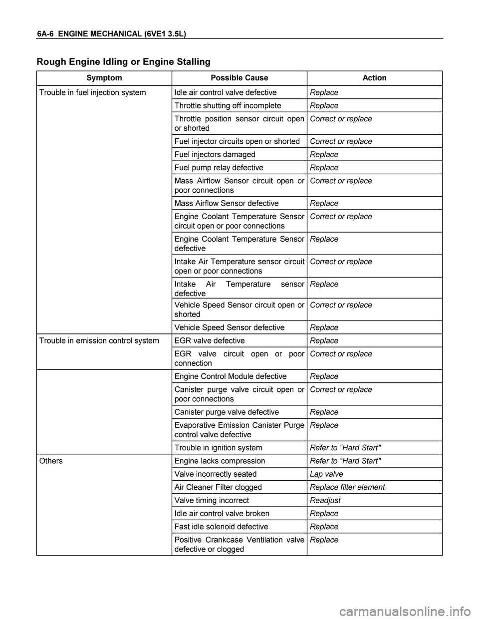
Rough Engine Idling or Engine Stalling
Symptom Possible Cause Action
Trouble in fuel injection system Idle air control valve defective Replace
Throttle shutting off incomplete Replace
Throttle position sensor circuit open
or shorted Correct or replace
Fuel injector circuits open or shortedCorrect or replace
Fuel injectors damaged Replace
Fuel pump relay defective Replace
Mass Airflow Sensor circuit open or
poor connections Correct or replace
Mass Airflow Sensor defective Replace
Engine Coolant Temperature Sensor
circuit open or poor connections Correct or replace
Engine Coolant Temperature Sensor
defective Replace
Intake Air Temperature sensor circuit
open or poor connections Correct or replace
Intake Air Temperature sensor
defective Replace
Vehicle Speed Sensor circuit open or
shorted Correct or replace
Vehicle Speed Sensor defective Replace
Trouble in emission control system EGR valve defective Replace
EGR valve circuit open or poor
connection Correct or replace
Engine Control Module defective Replace
Canister purge valve circuit open or
poor connections Correct or replace
Canister purge valve defective Replace
Evaporative Emission Canister Purge
control valve defective Replace
Trouble in ignition system Refer to “Hard Start"
Others Engine lacks compression Refer to “Hard Start"
Valve incorrectly seated Lap valve
Air Cleaner Filter clogged Replace filter element
Valve timing incorrect Readjust
Idle air control valve broken Replace
Fast idle solenoid defective Replace
Positive Crankcase Ventilation valve
defective or clogged Replace
Page 1831 of 4264
ENGINE MECHANICAL (6VE1 3.5L) 6A-7
Rough Engine Running
Symptom Possible Cause Action
Engine misfires periodically Ignition coil layer shorted Replace
Spark plugs fouling Clean or install hotter type plug
Spark plug(s) insulator nose leaking Replace
Fuel injector(s) defective Replace
Engine control module faulty Replace
Engine knocks periodically Spark plugs running too hot Install colder type spark plugs
Engine control module faulty Replace
Engine lacks power Spark plugs fouled Clean
Fuel injectors defective Replace
Mass Airflow Sensor or Intake Airflow
Sensor circuit defective Correct or replace
Engine Coolant Temperature Sensor
or Engine Coolant Temperature
Sensor circuit defective Correct or replace
Engine Control Module faulty Replace
Intake Air Temperature Sensor or
Intake Air Temperature Sensor circuit
defective Correct or replace
Throttle Position Sensor or Throttle
Position Sensor circuit defective Correct or replace
Page 1832 of 4264
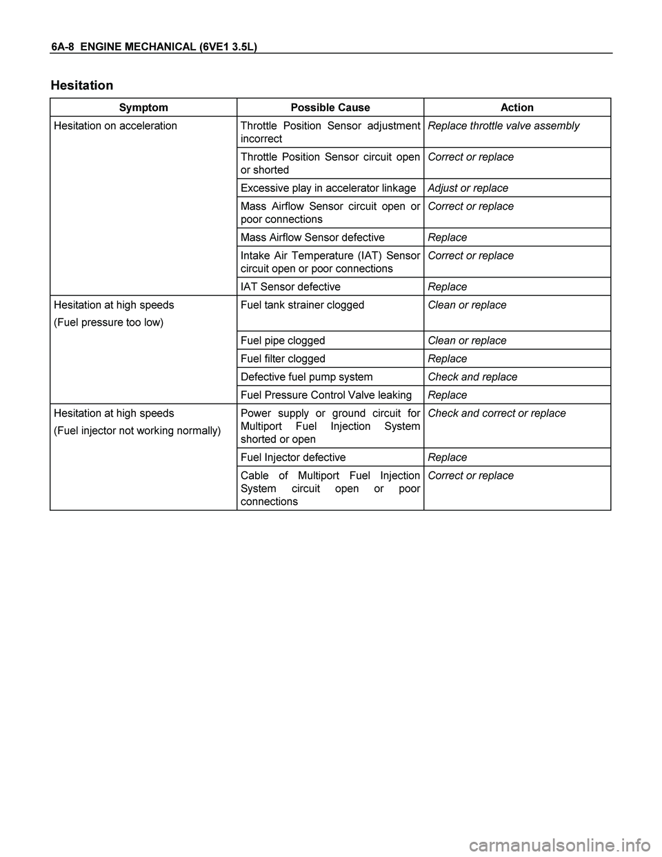
6A-8 ENGINE MECHANICAL (6VE1 3.5L)
Hesitation
Symptom Possible Cause Action
Hesitation on acceleration Throttle Position Sensor adjustment
incorrect Replace throttle valve assembly
Throttle Position Sensor circuit open
or shorted Correct or replace
Excessive play in accelerator linkageAdjust or replace
Mass Airflow Sensor circuit open or
poor connections Correct or replace
Mass Airflow Sensor defective Replace
Intake Air Temperature (IAT) Sensor
circuit open or poor connections Correct or replace
IAT Sensor defective Replace
Hesitation at high speeds
(Fuel pressure too low) Fuel tank strainer clogged Clean or replace
Fuel pipe clogged Clean or replace
Fuel filter clogged Replace
Defective fuel pump system Check and replace
Fuel Pressure Control Valve leaking Replace
Hesitation at high speeds
(Fuel injector not working normally) Power supply or ground circuit for
Multiport Fuel Injection System
shorted or open Check and correct or replace
Fuel Injector defective Replace
Cable of Multiport Fuel Injection
System circuit open or poor
connections Correct or replace
Page 1833 of 4264
ENGINE MECHANICAL (6VE1 3.5L) 6A-9
Symptom Possible Cause Action
Hesitation at high speeds Engine Control Module defective Replace
Throttle Position Sensor cable broken
or poor connections Correct or replace
Throttle Position Sensor defective Replace
Engine Coolant Temperature Sensor
circuit open or shorted Correct or replace
Engine Coolant Temperature Sensor
defective Replace
Mass Airflow Sensor circuit open or
poor connections Correct or replace
Mass Airflow Sensor defective Replace
IAT Sensor circuit open or poor
connections Correct or replace
IAT Sensor defective Replace
Throttle valve not fully opened Check and correct or replace
Air Cleaner Filter clogged Replace filter element
Power supply voltage too low Check and correct or replace