Page 1307 of 4264
:
A Bosch Distributor Type Injection Pump is used. A single reciprocating/revolving plunger delivers the fuel uniformly
to th")
FUEL SYSTEM 6C – 7
INJECTION PUMP
RTW46CLF000201
4JA1T(L):
A Bosch Distributor Type Injection Pump is used. A single reciprocating/revolving plunger delivers the fuel uniformly
to the injection nozzles, regardless of the number of cylinders.
The governor, the injection timer, and the feed pump are all contained in the injection pump housing. The injection
pump is compact, light weight, and provides reliable high-speed operation.
The vacuum-type fast idle actuator increases the engine idling speed to provide the additional power required to
operate the air conditioner.
Fast idler diaphragm movement is caused by changes in the negative pressure created by the engine’s vacuum
pump.
The diaphragm motion is transferred to the injection pump control lever to increase or decrease the idling speed.
4JA1TC/4JH1TC:
The Bosch VP44 injection pump is electronically controlled. The pump controller combine to injection pump.
Signals from the pump controller are sent to the engine control module (ECM). In response to these signals, the
ECM selects the optimum fuel injection timing and volume for the existing driving conditions.
Page 1308 of 4264
6C – 8 FUEL SYSTEM
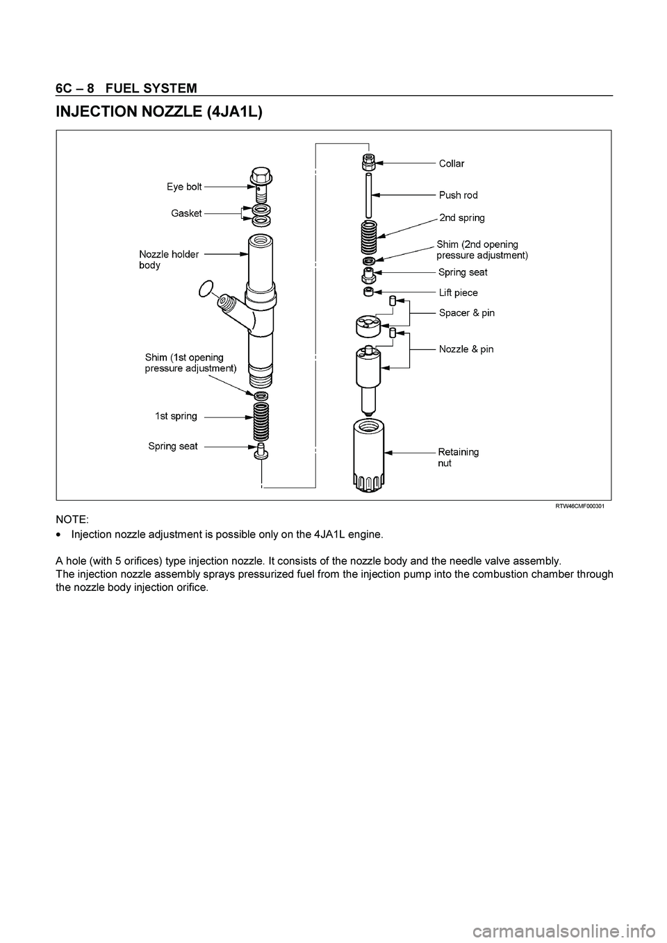
INJECTION NOZZLE (4JA1L)
RTW46CM F000301
NOTE:
�
Injection nozzle adjustment is possible only on the 4JA1L engine.
A hole (with 5 orifices) type injection nozzle. It consists of the nozzle body and the needle valve assembly.
The injection nozzle assembly sprays pressurized fuel from the injection pump into the combustion chamber through
the nozzle body injection orifice.
Page 1310 of 4264

6C – 10 FUEL SYSTEM
Removal
CAUTION: When repair to the fuel system has been
completed, start engine and check the fuel system for
loose connection or leakage. For the fuel system
diagnosis, see Section “Driveability and Emission".
1. Disconnect battery ground cable.
2. Loosen slowly the fuel filler cap.
NOTE: Be careful not to spouting out fuel because of change
the pressure in the fuel tank.
NOTE: Cover opening of the filler neck to prevent any dus
t
entering.
3. Jack up the vehicle.
4. Support underneath of the fuel tank with a lifter.
5. Remove the inner liner of the wheel house at rear left side.
6. Remove fixing bolt of the filler neck from the body.
7.
Disconnect the quick connector (3) of the fuel tube from the
fuel pipe.
NOTE: Cover the quick connector to prevent any dust entering
and fuel leakage.
NOTE: Refer to“Fuel Tube/Quick Connector Fittings” in this
section when performing any repairs.
8. Remove fixing bolt (1) of the tank band and remove the
tank band (2).
9.
Disconnect the pump and sender connector on the fuel
pump and remove the harness from weld clip on the fuel
tank.
10.
Lower the fuel tank (5).
NOTE: When lower the fuel tank from the vehicle, don’t scratch
each hose and tube by around other parts.
Installation
1. Raise the fuel tank.
NOTE: When raise the fuel tank to the vehicle, don’t scratch
each hose and tube by around other parts.
2. Connect the pump and sender connector to the fuel pump
and install the harness to weld clip on the tank.
NOTE: The connector must be certainly connected agains
t
stopper.
3. Install the tank band and fasten bolt.
Torque N·m (kg·m / lb ft)
68 (6.9 / 50)
NOTE: The anchor of the tank band must be certainly installed
to guide hole on frame.
4. Connect the quick connector of the fuel tube to the fuel pipe
and the evapo tube from evapo joint connector.
NOTE: Pull off the left checker on the fuel pipe.
NOTE: Refer to “Fuel Tube/Quick Connector Fittings” in this
section when performing any repairs.
Page 1313 of 4264

FUEL SYSTEM 6C – 13
Removal
CAUTION: When repair to the fuel system has been
completed, start engine and check the fuel system for
loose connection or leakage. For the fuel system
diagnosis, see Section “Driveability and Emission".
1. Remove fuel tank assembly (9). Refer to “Fuel Tank
Removal" in this section.
2. Disconnect the quick connector (6) of the fuel tube from fuel
gauge unit.
3. Disconnect the quick connector (10) of the evapo tube from
fuel gauge unit.
140R100035
3. Remove the retainer ring (7) from the fuel tank with the
removal tool 5-8840-2602-0.
4.
Remove slowly the fuel gauge unit (4) from the fuel tank as
no bend float arm.
NOTE: Cover opening for the fuel gauge unit on fuel tank to
prevent any dust entering.
5.
Discard fuel gauge unit seal (8) because it cannot be
reusable.
Installation
1. Clean the seal surface of the fuel tank and the fuel gauge
unit.
NOTE: If there is dust on the seal surface, it becomes cause o
f
fuel leak.
2. Install the new fuel gauge unit seal (8) to opening of the fuel
tank as along the groove.
3. Install slowly the fuel gauge unit (4) into the fuel tank as no
bend float arm.
4.
Set flange of the fuel gauge unit on fuel gauge unit seal as
mating convexity of the fuel gauge unit and reentrant of the
fuel tank.
5.
Lock slowly the retainer ring (7) to the fuel tank with the
remover tool 5-8840-2602-0.
6. Connect the quick connector (10) of the evapo tube from
fuel gauge unit.
7.
Connect the quick connector (6) of the fuel tube to to gauge
unit.
NOTE: Pull off the left ckecker of the fuel pipe.
NOTE: Refer to “Fuel Tube/Quick Connector Fittings” in this
section when performing any repairs.
Page 1316 of 4264

6C – 16 FUEL SYSTEM
140R100037
2. For removal of the quick connector, hold the quick
connector in one hand, and pull out the connector with the
other hand while pressing the square relieve button of the
connector, as illustrated.
NOTE: Do not use tools of any kind. Only use bare hands
when disconnecting the connector. Use a lubricant (light oil)
and/or push and pull the connector until the pipe is
disconnected.
140R100028
Cover the connectors that was removed with a plastic bag,
to prevent dust or rain water from entering.
140R100036
Reuse of Quick–Connector
�
Replace the port and connector if scratch, dent or crack is
found.
� Remove any dirt build up on the port when installing the
connector. Replace the connector, if there is any forms o
f
rust, dent, scratch.
�
After cleaning the port, insert it straight into the connector
until it clicks. After it clicks, try pulling at 49N (5kgf) it out to
make sure that it is not drawn and is securely locked.
Assembling Advice
By applying engine oil or light oil to the pipe, port makes pipe
assembly easier. The pipe assembly should take place
immediately after applying oil (to prevent dust from sticking to
the pipe surface – which may decrease sealing ability).
Test/Inspection After Assembling
1. Reconnect the battery negative cable.
2. Start the engine and observe the engine idle speed. The
presence of dirt in the fuel system may affect the fuel
injection system.
3. Check for fuel leakage from the connector.
Page 1318 of 4264
6C – 18 FUEL SYSTEM
FUEL FILLER CAP
RTW36CSH000401
Legend
(1)
Pressure Valve
(2)
Vacuum Valve
(3)
Seal Ring
General Description
A vacuum valve and pressure valve are built into the fuel filler
cap which adjusts the fuel pressure in the fuel tank to prevent
fuel tank damage.
Inspection
The fuel filler cap must be inspected for seal condition.
The fuel filler cap must be replaced if found defective
CAUTION: A replacement fuel filler cap must be the same
as the original. The fuel filler cap valve was designed
primarily for this application and must be replaced with
the same type or decreased engine performance may
occur.
Page 1326 of 4264
6C – 26 FUEL SYSTEM
INJECTION NOZZLE (4JA1L)
DISASSEMBLY
080L200009
Disassembly Steps
1.
Retaining nut 9.
Collar
2.
Nozzle & pin 10.
Spring seat
3.
Spacer & pin 11.
First spring
4.
Lift Piece 12.
Shim (First nozzle opening
pressure adjustment)
5.
Spring seat 13.
Nozzle holder body
6.
Push rod 14.
Eye bolt
7.
Shim (Second nozzle opening
pressure adjustment) 15.
Gasket
8.
Second spring
Important Operations
Injection nozzle adjustment is possible only on the 4JA1L
engine.
The two-spring nozzle holder has been developed to
reduce NOx (Nitrogen Oxides) and particulates from direct
injection diesel engine exhaust.
Before disassembly remove carbon deposit from nozzle
and nozzle holder using a wire brush and wash the outside
nozzle holder assembly.
Caution:
Do not touch nozzle holes with the wire brush during
cleaning it.
Disassemble the nozzle holder assembly to numerical
order.
Page 1339 of 4264

ENGINE ELECTRICAL 6D – 1
SECTION 6D
ENGINE ELECTRICAL
TABLE OF CONTENTS
PAGE
Main Data and Specifications ......................................................................................... 6D - 2
General Description......................................................................................................... 6D - 3
Torque Specifications ..................................................................................................... 6D - 5
Generator.......................................................................................................................... 6D - 7
Removal and Installation ............................................................................................ 6D - 7
Disassembly................................................................................................................. 6D - 9
Inspection and Repair ................................................................................................. 6D - 12
Reassembly.................................................................................................................. 6D - 18
Starter Motor .................................................................................................................... 6D - 22
Removal and Installation ............................................................................................ 6D - 22
Disassembly................................................................................................................. 6D - 23
Inspection and Repair ................................................................................................. 6D - 26
Reassembly.................................................................................................................. 6D - 29
Pre-heating System ......................................................................................................... 6D -33
Inspection and Repair ................................................................................................. 6D -33
Glow Relay ................................................................................................................... 6D -33
Glow Plug ..................................................................................................................... 6D -33
EGR System ................................................................................................................. 6D -33

Pressure Valve
(2)
Vacuum Valve
(3)
Seal Ring
General Description
A vacuum valve and pressure valve")

DISASSEMBLY
080L200009
Disassembly Steps
1.
Retaining nut 9.
Collar
2.
Nozzle & pi")