Page 1340 of 4264
6D – 2 ENGINE ELECTRICAL
MAIN DATA AND SPECIFICATIONS
Description
Item
60A 80A
Generator
Type
AC generator with IC regulator and vacuum pump
Hitachi LR160-503E Hitachi LR180-513B
Voltage V
Drive and rotation
Ground polarity 12
V-belt, clockwise viewed from the drive pulley
Negative
Maximum output A 60 80
Engine speed ratio to 1 1.788
Maximum speed rpm 11,000
Weight with vacuum pump kg(lb) 5.8(12.8) 6.4(14.1)
Vacuum Pump
Delivery volume cm3/rev
Exhaust Characteristic
Maximum vacuum
50
-66.7 kPa (-500 mmHg) bulid up time 21 seconds or less at 1,000
rpm
7 seconds or less at 5,000 rpm
-90.7 kPa (-680 mmHg) or more
Starter Motor
Type
Solenoid controlled
Hitachi S13-555
12
2.3
8.76
300 Rated voltage V
Rated output kW
Load characteristics
Terminal voltage V
Load current A
Weight kg(Ib)
4.7 (10.4)
Page 1341 of 4264
ENGINE ELECTRICAL 6D – 3
GENERAL DESCRIPTION
GENERATOR STARTER MOTOR
066L300004065L300002
The basic charging system is the IC integral regulator charging system. The internal components are connected
electrically as shown in charging circuit diagram.
The generator features a solid state regulator that is mounted inside the generator. All regulator components are
enclosed into a solid mold, and this unit along with the brush holder assembly is attached to the slip ring end frame.
The generator voltage setting cannot be adjusted.
The starter motor circuit is composed of a 4-pole 4-brush type direct current series motor. The starter motor circuit
utilizes negative ground polarity.
Page 1342 of 4264
6D – 4 ENGINE ELECTRICAL
CHARGING CIRCUIT DIAGRAM
RTW46DSH005101
STARTING CIRCUIT DIAGRAM
RTW46DSH005501
Page 1343 of 4264
ENGINE ELECTRICAL 6D – 5
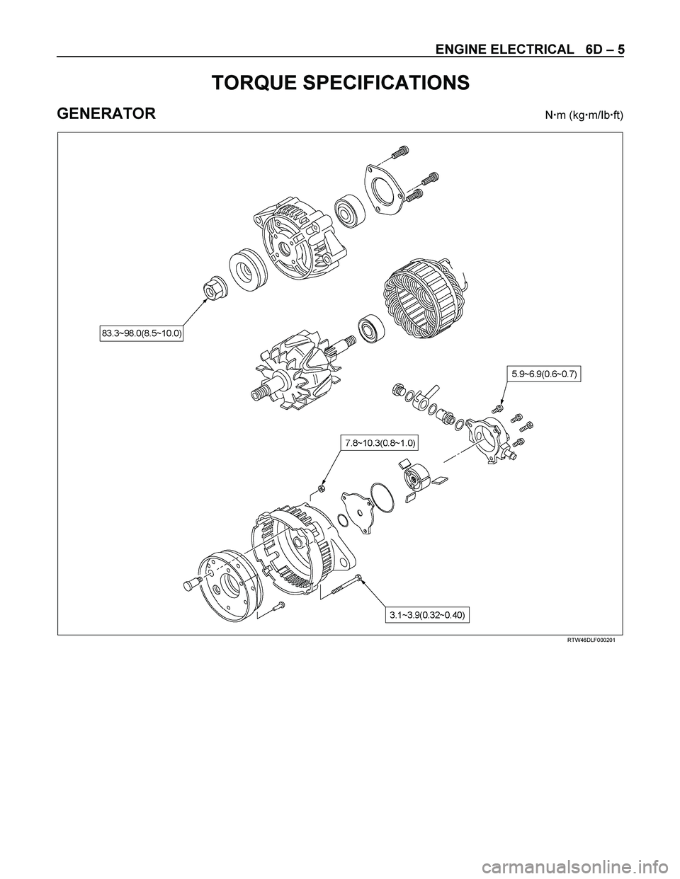
TORQUE SPECIFICATIONS
GENERATOR N�m (kg�m/Ib�ft)
RTW46DLF000201
Page 1344 of 4264
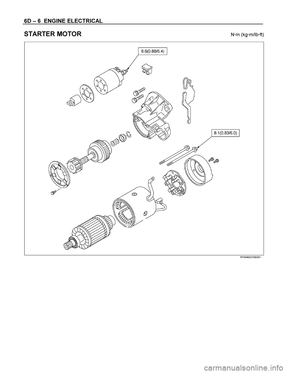
6D – 6 ENGINE ELECTRICAL
STARTER MOTOR N�m (kg�m/Ib�ft)
RTW46DLF000301
Page 1345 of 4264

ENGINE ELECTRICAL 6D – 7
GENERATOR
REMOVAL AND INSTALLATION
Read this Section carefully before performing any removal and installation procedure. This Section gives you
important points as well as the order of operation. Be sure that you understand everything in this Section before you
begin.
P1010002
Important Operations-Removal
Cooling Fan Belt
1. Disconnect the battery cables at the battery terminals.
2. Loosen and remove the fan belt adjusting plate bolts.
3. Remove the fan belt from the generator drive pulley.
Generator
1. Remove the vacuum pump hose.
2. Remove the generator bolt and the generator from the bracket.
Important Operations-Installation
Follow the removal procedure in the reverse order to
perform the installation procedure. Pay careful attention to
the important points during the installation procedure.
Generator
1. Install the generator to the bracket.
2. Tighten the generator bolt to the specified torque.
3. Install the vacuum pump hose.
Generator Bolt Torque N �m (kg �m/Ib �ft)
40 (4.1/30)
Page 1346 of 4264
6D – 8 ENGINE ELECTRICAL
033RY00009
Cooling Fan Drive Belt
1. Hold the generator toward the engine.
2. Install the fan belt to the three pulleys.
1 Crankshaft pulley
2 Generator pulley
3 Cooling fan drive pulley
3. Adjust the fan belt tension
Fan belt tension is adjusted by moving the generator.
Depress the drive belt mid-portion with a 98N (10
kg/22 Ib) force.
Cooling Fan Drive Belt Deflection mm (in)
New belt 4 - 7 (0.16 - 0.28)
Reuse belt 6 - 9 (0.24 - 0.35)
4. Tighten the adjusting plate bolts to the specified
torque.
Adjusting Plate Bolt N·m (kg·m/lb·ft)
19 (1.9/14)
5. Reconnect the battery cable to the battery.
Page 1347 of 4264
ENGINE ELECTRICAL 6D – 9
DISASSEMBLY
RTW46DLF000401
Disassembly Step
1.
Vacuum pump
2.
O-ring
3.
Through bolt
4.
B Terminal nut
5.
Rear cover
6.
Pulley
7.
Rotor assembly
8.
Front cover assembly
9.
Rear rotor bearing
10.
Rectifier assembly
11.
Stator assembly
12.
Rotor assembly