Page 1364 of 4264

6D – 26 ENGINE ELECTRICAL
INSPECTION AND REPAIR
Make the necessary adjustments, repairs, and part replacement if excessive wear or damage is discovered during
inspection.
ARMATURE
1. Measure the commutator run-out. Replace the commutator if the measured run-out
exceeds the specified limit.
Commutator Run-Out mm (in)
Standard Limit
0.05 (0.002) 0.2 (0.008)
RTW46DSH003501
2. Check the commutator mica segments for excessive
wear.
3. Measure the mica segment depth.
Mica Segment Depth mm (in)
Standard Limit
0.5 � 0.8 (0.020 � 0.030) 0.2 (0.008)
065RY00025
If the mica segment depth is less than the standard but
more than the limit, the commutator may be reground.
If the mica segment depth is less than the limit, the
commutator must be replaced.
4. Measure the commutator outside diameter.
Commutator Outside Diameter mm (in)
Standard Limit
36.5 (1.44) 35.5 (1.40)
If the measured outside diameter is less than the specified
limit, the commutator must be replaced.
065RY00026
RTW46DSH003601
5. Use a circuit tester to check the armature for
grounding.
1 Hold one probe of the circuit tester against the commutator segment.
2 Hold the other circuit tester probe against the armature core.
If the circuit tester indicates continuity, the armature is grounded.
The armature must be replaced.
Page 1365 of 4264

ENGINE ELECTRICAL 6D – 27
RTW46DSH003701
6. Use the circuit tester to check the armature for
continuity.
1 Hold the circuit tester probes against two
commutator segments.
2 Repear Step 1 at different segments of the
armature core.
There should be continuity between all segments of
the commutator.
If there is not, the armature must be replaced.
RTW46DSH003801
YOKE
1. Use a circuit tester to check the field winding ground.
1 Hold one circuit tester probe against the field
winding end or brush.
2 Hold the other circuit tester probe against the bare
surface of the yoke body.
There should be no continuity.
If there is continuity, the field coil is grounded.
The yoke must be replaced.
RTW46DSH003901
2. Use the circuit tester to check the field winding
continuity.
1 Hold one circuit tester probe against the “M”
terminal lead wire.
2 Hold the other circuit tester probe against the field
winding brush.
There should be continuity.
If there is no continuity, the yoke must be replaced.
Page 1366 of 4264
.
Replace the brushes as a set if one or more of the
brush lengths is less")
6D – 28 ENGINE ELECTRICAL
BRUSH AND BRUSH HOLDER
1. Use a vernier caliper to measure the brush length (four
brushes).
Replace the brushes as a set if one or more of the
brush lengths is less than the specified limit.
Brush Length mm (in)
Standard Limit
15 (0.59) 12 (0.47)
RTW46DSH004001
RTW46DSH004101
2. Use a circuit tester to check the brush holder
insulation.
Touch one probe to the holder plate and the other
probe to the positive brush holder.
There should be no continuity.
3. Inspect the brushes for excessive wear.
If the negative brushes have excessive wear, the
entire brush holder assembly must be replaced.
If the positive brushes have excessive wear, the entire
yoke must be replaced.
OVERRUNNING CLUTCH
1. Inspect the overrunning clutch gear teeth for
excessive wear and damage.
Replace the overrunning clutch if necessary.
2. Rotate the pinion clockwise.
It should turn smoothly.
3. Try to rotate the pinion in the opposite direction.
The pinion should lock.
065RY00035
RTW46DSH004401
BEARING
Inspect the bearings for excessive wear and damage.
Replace the bearings if necessary.
Page 1367 of 4264
ENGINE ELECTRICAL 6D – 29
REASSEMBLY
RTW46DLF000601
Reassembly Steps
1.
Magnetic switch assembly
14. Pinion stopper
2.
Magnetic switch 15. Pinion stopper clip
3.
Dust cover 16. Bearing retainer
4.
Plunger 17. Bolt
5.
Torsion spring 18. Motor assembly
6.
Shift lever
19. Armature
7.
Gear case 20. Yoke
8.
Dust cover 21. Brush holder
9.
Bolt 22. Rear cover
10.
Pinion assembly 23. Screw
11.
Clutch 24. Through bolt
12.
Pinion shaft 25. Lead wire
13.
Rerurn spring
Page 1368 of 4264
6D – 30 ENGINE ELECTRICAL
RTW46DSH005601
Important Operations
1. Magnetic Switch Assembly
1. Attach the torsion spring to the hole in the magnetic
switch as illustrated.
2. Insert the shift lever into the plunger hole of the
magnetic switch.
RTW46DSH005701
7. Gear Case
3,8. Dust Cover
1. Install the magnetic switch assembly in the gear case.
2. Install the dust cover.
Dust Cover Bolt Torque N�m (kg�m/lb�ft)
8 (0.8/5.4)
10. Pinion Assembly
Apply a coat of grease to the reduction gear and install the
pinion assembly to the armature shaft.
065RY00041
RTW46DSH004501
21. Brush Holders
1. Install the brushes into the brush holder with raising
the spring end of the brush spring.
Take care not to damage the commutator face.
2. Install the brush holder with aligning the peripheries of
the yoke and the brush holder.
Page 1369 of 4264
ENGINE ELECTRICAL 6D – 31
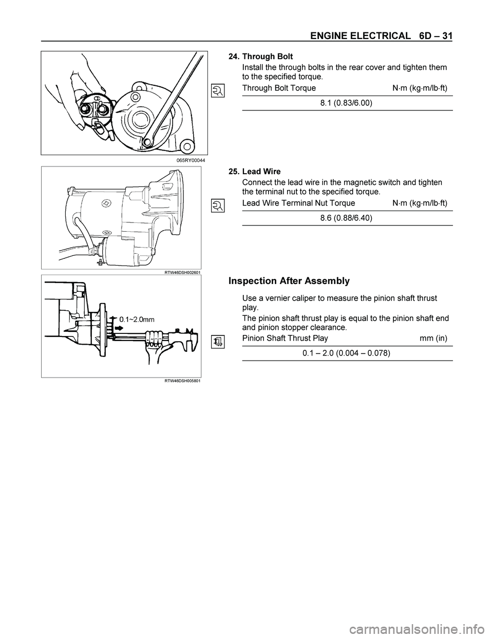
24. Through Bolt
Install the through bolts in the rear cover and tighten them
to the specified torque.
Through Bolt Torque N�m (kg�m/lb�ft)
8.1 (0.83/6.00)
065RY00044
RTW46DSH002601
25. Lead Wire
Connect the lead wire in the magnetic switch and tighten
the terminal nut to the specified torque.
Lead Wire Terminal Nut Torque N�m (kg�m/lb�ft)
8.6 (0.88/6.40)
RTW46DSH005801
Inspection After Assembly
Use a vernier caliper to measure the pinion shaft thrust
play.
The pinion shaft thrust play is equal to the pinion shaft end
and pinion stopper clearance.
Pinion Shaft Thrust Play mm (in)
0.1 – 2.0 (0.004 – 0.078)
Page 1370 of 4264
6D – 32 ENGINE ELECTRICAL
MAGNETIC SWITCH
The following tests must be performed with the starter
motor fully assembled.
The yoke lead wire must be disconnected from the “M”
terminal.
To prevent coil burning, complete each test as quickly as
possible (within three to five seconds).
RTW46DSH004601
Temporarily connect the solenoid switch between the
clutch and the housing and run the following test.
Complete each test within three to five seconds.
1. Pull-in Test
Connect the battery negative terminal with the solenoid
switch body and the M terminal. When current is applied to
the S terminal from the battery positive terminal, the pinion
should flutter.
RTW46DSH005901
2. Hold-in Maintenance Test
Disconnect the lead at the M terminal. The pinion should
continue to flutter.
RTW46DSH004701
3. Return Test
Disconnect the battery positive lead at the S terminal.
The pinion should return to its home position.
Page 1371 of 4264
ENGINE ELECTRICAL 6D – 33
PRE-HEATING SYSTEM
INSPECTION AND REPAIR
Make the necessary adjustments, repairs, and part replacement if excessive wear of damage is discovered during
inspection.
VISUAL CHECK
Check the main fuses and glow indicator for damage.
Replace the part(s) if required.
GLOW RELAY
The glow relay is located in the relay box the engine
compartment.
825R300046
Use an ohmmeter to measure the resistance between
terminals No.2 and No.3.
If the measured value is outside the specified range, the
glow relay must be replaced.
Glow Relay Resistance Ohms
94 � 114
GLOW PLUG
LNW21KSH001401
Use a circuit tester to test the glow plugs for continuity.
Glow Plug Resistance (Reference) Ohms
Approximately 0.9
EGR SYSTEM 4JA1T (L)
Refer to 6F-9. (EGR system diagram)