Page 1031 of 4264
ELECTRICAL-BODY AND CHASSIS 8A-373
ANTI-LOCK BRAKE SYSTEM
PARTS LOCATION (RHD)
RTW48AXF022101 & RTW48AXF022201
Page 1081 of 4264
ELECTRICAL-BODY AND CHASSIS 8A-423
No. Connector face No. Connector face
C-36
Silver
Engine room-LH ; Ground C-54
(6VE1)
(4JH1-TC)
OrangeABS sensor Front-LH
C-37
Black
Brake fluid level switch C-55
BrownThermo AMP
C-38
(4JH1-TC)
Vacuum switch C-56
(C24SE)
ECM
C-39
Parking brake switch (stick type) C-56
(4JA1-TC
4JH1-TC)
ECM-A
C-40
~
C-43 NOT USED C-57
(4JA1-TC
4JH1-TC)
ECM-B
C-44
White
Stop lamp switch C-58
~
C-62 NOT USED
C-45
~
C-49 NOT USED C-63
(6VE1)
(4JH1-TC)
Gray Front Fog lamp-RH
C-50
Condenser fan C-64
(6VE1)
(4JH1-TC)
Gray Front Fog lamp-LH
C-51
~
C-52 NOT USED C-65
~
C-66 NOT USED
C-53
(6VE1)
(4JH1-TC)
Orange ABS sensor Front-RH C-67
(6VE1)
(4JH1-TC)
BlackEHCU
Page 1096 of 4264
8A-438 ELECTRICAL-BODY AND CHASSIS
No. Connector face No. Connector face
R-1
Black
Front door switch-LH R-12
Pretensioner - RH
R-2
NOT USED R-13
Pretensioner - LH
R-3
Gray
Seat belt switch R-14
2-4WD control
R-4
Natural
Parking brake switch (Lever type) R-15
2-4WD control
R-5
NOT USED
R-6
Black
Front door switch-RH
R-7
~
R-8 NOT USED
R-9
Black
Rear speaker-LH
R-10
Black
Rear speaker-RH
R-11
Seat belt switch
Page 1099 of 4264

CRUISE CONTROL SYSTEM 8B-1
SECTION 8B
CRUISE CONTROL SYSTEM
TABLE OF CONTENTS
PAGE
Service Precaution .........................................................................................................................8B- 3
General Description .......................................................................................................................8B- 3
Brake Switch ...................................................................................................................................8B- 5
Removal .......................................................................................................................................8B- 5
Installation ..................................................................................................................................8B- 5
Adjustment ..................................................................................................................................8B- 6
Clutch switch ...................................................................................................................................8B- 6
Removal and Installation ........................................................................................................8B- 6
Adjustment ..................................................................................................................................8B- 6
Starter Switch ..................................................................................................................................8B- 6
Removal .......................................................................................................................................8B- 6
Installation ..................................................................................................................................8B- 6
Cruise Control Main Switch .........................................................................................................8B- 7
Removal .......................................................................................................................................8B- 7
Installation ..................................................................................................................................8B- 7
Cruise Control Switch (Combination Switch) ........................................................................8B- 7
Removal and Installation ........................................................................................................8B- 7
Cruise Control Unit ........................................................................................................................8B- 8
Removal .......................................................................................................................................8B- 8
Installation ..................................................................................................................................8B- 8
Cruise Actuator ...............................................................................................................................8B- 8
Actuator Cable Diagram ..........................................................................................................8B- 9
Removal .......................................................................................................................................8B- 9
Installation ..................................................................................................................................8B- 9
Adjustment ..................................................................................................................................8B- 9
Mode Switch ....................................................................................................................................8B- 9
Removal and Installation ........................................................................................................8B- 9
Page 1102 of 4264

8B-4 CRUISE CONTROL SYSTEM
2. RESUME/ACCEL Switch Function
1. Resume Function: When the RESUME/ACCEL switch is turned on/off after the system is temporarily
deactivated by pressing the brake or clutch pedal while the vehicle is running, the vehicle resumes the speed
stored before the system was released, and the vehicle automatically runs at the stored speed.
2. Accelerate Function: When the RESUME/ACCEL switch is kept on the vehicle accelerates its speed during
that time. The vehicle speed at which the vehicle was running when the switch was turned off is stored in the
memory, and the vehicle automatically returns to this speed.
3. Tap-up Function: When the RESUME/ACCEL switch is turned on and off instantaneously while the vehicle
is running, the vehicle decelerates a mile for each on/off operation. The vehicle speed at which the vehicle
was running when the switch was turned off last is stored in the memory, and the vehicle automatically
returns to this stored speed.
3. CANCEL Function
1. Temporary Cancellation:
� Brake pedal is pressed.
� Clutch pedal is pressed. (M/T)
� Select lever is shifted to any position other than “D”, “3”, “2” or “L”. (A/T)
� Cancel switch is operated.
� Vehicle speed exceeds about 12.5mph over the vehicle speed stored in the memory.
Turning the RESUME/ACCEL switch will return the vehicle to the speed stored in the cruise control memory.
2. Complete Cancellation:
� Starter switch or the main switch is turned off.
� Fail-safe function is activated.
� Vehicle speed is about 38 km/h mph.
� Speed becomes 20 (12.5) km/h (mph) or less form the speed memorized by Control unit.
Page 1103 of 4264
CRUISE CONTROL SYSTEM 8B-5
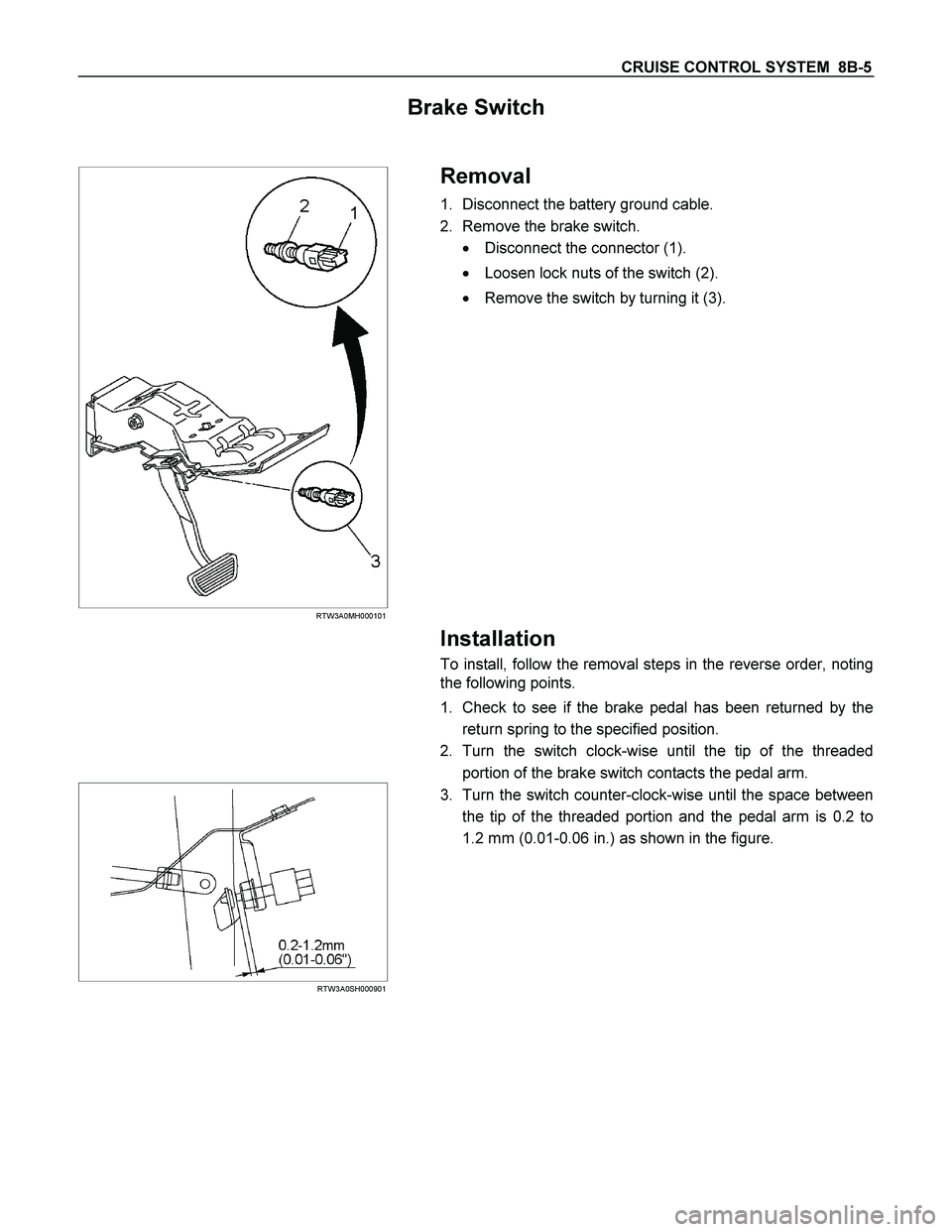
Brake Switch
RTW3A0MH000101
Removal
1. Disconnect the battery ground cable.
2. Remove the brake switch.
� Disconnect the connector (1).
� Loosen lock nuts of the switch (2).
� Remove the switch by turning it (3).
Installation
To install, follow the removal steps in the reverse order, noting
the following points.
1. Check to see if the brake pedal has been returned by the
return spring to the specified position.
2. Turn the switch clock-wise until the tip of the threaded
portion of the brake switch contacts the pedal arm.
RTW3A0SH000901
3. Turn the switch counter-clock-wise until the space between
the tip of the threaded portion and the pedal arm is 0.2 to
1.2 mm (0.01-0.06 in.) as shown in the figure.
Page 1104 of 4264

8B-6 CRUISE CONTROL SYSTEM
Adjustment
1. Check to be sure that the brake pedal has been completely
returned by the return spring.
2. Disconnect the switch connector.
RTW3A0SH001201
3. Release the lock (2) by turning the switch (1) counter-clock-
wise.
4. After doing so, pull the pedal arm (3) to you a little so tha
t
the pedal arm is not pushed in.
5. Making the pedal arm not movable with one hand, push in
the whole switch with the other hand until the plunger of the
switch is pushed in and the switch itself hits the rubber o
f
the pedal arm.
In the condition, turn the switch clock-wise until "click"
sound is made and lock it.
By doing this, the switch is adjusted at 0.2 to 1.2mm (0.01-
0.06 in.) clearance.
Clutch Switch
Removal and Installation
Refer to the Clutch Control removal and installation steps in
Clutch section.
Adjustment
1. Turn the clutch switch or stopper bolt 1 until the switch bolt
or stopper bolt just touches the clutch pedal arm.
2. Adjust clutch switch or stopper bolt by backing it out half a
turn, and measure the clearance (L) between the clutch
pedal arm and the clutch switch bolt end or stopper bolt.
3. Lock the lock nut
2.
4. Connect the clutch switch connector.
Clutch switch and clutch and clutch pedal clearance
mm (in)
Limit 0.5-1.5 (0.020-0.059)
Starter Switch
431R300001
Removal
1. Steering Lock Assembly
� Refer to the Steering Lock assembly removal steps o
f
"Steering Column" in Power-Assisted Steering System
section.
2. Starter Switch
Installation
Follow the removal procedure in the reverse order to install the
starter switch.
Page 1112 of 4264
 YES NO
1
1. Turn the starter switch off.
2. Disconnect the actuator connector C–119.
3. Mea")
8B-14 CRUISE CONTROL SYSTEM
DTC 1–2 Clutch System Open or Short Circuit
Step Action Value(s) YES NO
1
1. Turn the starter switch off.
2. Disconnect the actuator connector C–119.
3. Measure resistance between actuator side
connector terminal 3 and 4.
Is there resistance within range specified in the
value(s) column?
34.7 –
42.4�
Go to Step 2
Replace the
actuator
2
1. Disconnect the brake switch connector C–44.
2. Check continuity between switch side connector
terminal 3 and 4.
Is there continuity between terminals?
—
Go to Step 3
Replace the
switch
3
1. Reconnect the brake switch connector C–44.
2. Check continuity between harness side connector
C–120 terminal 6 and connector C–44 terminal 3,
connector C–119 terminal 4 and connector C–120
terminal 8.
Is there continuity between terminals?
—
Go to Step 4
Replace open
circuit
4 Check continuity between harness side connector
C–119 terminal 3 and the ground, connector C–119
terminal 4 and the ground, connector C–120
terminal 6 and the ground.
Are the results same as specified in the value(s)
column?
No
continuity
Replace the
control unit
Repair short
circuit

RTW48AXF022101 & RTW48AXF022201")

(4JH1-TC)
OrangeABS sensor Front-LH
C-37
Black
Brake fluid leve")