Page 538 of 4264
10-30 CAB
12. Instrument Panel & Cross Beam Assembly
1) Remove the two bolts fixing the steering column to the
cross beam and the two bolts fixing the brake pedal
bracket to the cross beam.
2) Remove the two bolts fixing the parking brake bracket to
the cross beam (Stick type parking brake only).
3) Disconnect the control cables at the blower unit and
heater unit.
Remove the front & side cover from the instrumen
t
panel.
4) Remove the fasteners fixing the instrument panel &
cross beam assembly to the body panel.
5) Disconnect the instrument harness connectors.
Page 541 of 4264
CAB 10-33
Important Operations
15. Instrument Panel & Crass Beam Assembly
1) Tighten the 4 bolts fixing the cross beam and body panel
to the specified torque.
Torque N�
m (kgf�
m/lb�
ft)
19 (1.9/14)
2) A Bolt: Steering Column to Cross Beam
Torque N�
m (kgf�
m/lb�
ft)
20 (2.0/14)
B Bolt: Pedal Bracket to Cross Beam
Torque N�
m (kgf�
m/lb�
ft)
15 (1.5/11)
3) C Bolt: Parking Brake Bracket to Cross Beam
Torque N�m (kgf�m/lb�ft)
15 (1.5/11)
21. Steering Wheel/Steering Cowl
� Tighten the steering wheel fixing nut to the specified
truque.
Torque N�
m (kgf�
m/lb�
ft)
35 (3.6/26)
Page 622 of 4264
7C-20 CLUTCH
AIR BLEEDING
Bleed air from clutch operating cylinder according to the
following procedure.
Carefully monitor fluid level at master cylinder during bleeding
operation.
1. Set the paking brake.
2. Top up reservoir with recommended brake fluid.
3. Connect a transparent vinyl tube to air bleeder valve.
4. Fully depress clutch pedal several times.
5. With clutch pedal depressed, open bleeder valve to release
air.
6. Close bleeder valve.
7. Repeat steps 5 through 6 above until brake fluid flows from
air bleeder valve without air bubbles.
8. Bleed air from clutch damper according to the above
procedure.
9. Repeat the above bleeding procedure until the air
completely removed.
Page 637 of 4264
CLUTCH 7C-35
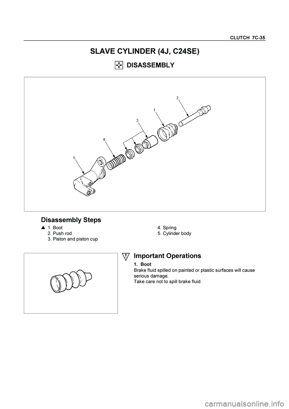
SLAVE CYLINDER (4J, C24SE)
DISASSEMBLY
Disassembly Steps
�
1. Boot
2. Push rod
3. Piston and piston cup
4. Spring
5. Cylinder body
Important Operations
1. Boot
Brake fluid spilled on painted or plastic surfaces will cause
serious damage.
Take care not to spill brake fluid.
Page 639 of 4264
CLUTCH 7C-37
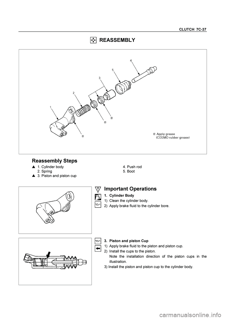
REASSEMBLY
Reassembly Steps
�
1. Cylinder body
2. Spring
�
3. Piston and piston cup
4. Push rod
5. Boot
Important Operations
1. Cylinder Body
1) Clean the cylinder body.
2) Apply brake fluid to the cylinder bore.
3. Piston and piston Cup
1) Apply brake fluid to the piston and piston cup.
2) Install the cups to the piston.
Note the installation direction of the piston cups in the
illustration.
3) Install the piston and piston cup to the cylinder body.
Page 661 of 4264

ELECTRICAL-BODY AND CHASSIS 8A-3
PAGE
Power Window ........................................................................................................... 8A- 310
Audio, Clock and Cigarette Lighter .......................................................................... 8A- 329
Power Door Mirror ...................................................................................................... 8A- 337
Rear Defogger ............................................................................................................ 8A- 349
SRS-Air Bag ................................................................................................................ 8A- 358
Transfer Case Control Module .................................................................................. 8A- 361
Anti-Lock Brake System ............................................................................................ 8A- 373
Immobilizer ................................................................................................................. 8A- 376
Keyless Entry ............................................................................................................. 8A- 385
Anti Theft ....................................................................................................................8A- 400
Auto Cruise ................................................................................................................. 8A- 412
Trailer Hitch ................................................................................................................ 8A- 415
Connector List ................................................................................................................8A- 418
Page 670 of 4264
 LH Left hand
ABS Anti-lock brake system LWB Long wh")
8A-12 ELECTRICAL-BODY AND CHASSIS
ABBREVIATIONS
Abbreviation Meaning of abbreviation Abbreviation Meaning of abbreviation
A Ampere (S) LH Left hand
ABS Anti-lock brake system LWB Long wheel base
ASM Assembly MPI Multipart fuel injection
AC Alternating current M/T Manual transmission
A/C Air conditioner QOS Quick On Start system
ACC Accessories RH Right hand
CARB Carburetor RR Rear
C/B Circuit breaker RWAL Rear wheel anti-lock brake system
CSD Cold start device SRS Supplemental restraint system
DIS Direct ignition system ST Start
EBCM Electronic brake control module STD Standard
ECGI Electronic control gasoline injection SW Switch
ECM Engine control module SWB Short wheel base
ECU Electronic control unit TCM Transmission control module
EFE Early fuel evaporation V Volt
4�2 Two-wheel drive VSV Vacuum switching valve
4�4 Four-wheel drive W Watt (S)
FL Fusible link WOT Wide open throttle
FRT Front W/ With
H/L Headlight W/O Without
IC Integrated circuit
IG Ignition
kW Kilowatt
Page 678 of 4264

8A-20 ELECTRICAL-BODY AND CHASSIS
Caution:
Never push or tow the vehicle in an attempt to start it.
Extensive damage to the emission system and other
vehicle parts will result.
(Only catalytic converter vehicle)
Treat both the discharged battery and the booster battery
with great care when using jumper cables.
Carefully follow the procedure outlined below.
Always be aware of the dangers of sparking.
Failure to follow the following procedure can result in:
a. Serious personal injury, specially to your eyes.
b. Extensive property damage from a battery explosion,
battery acid discharge, or electrical file.
c. Extensive damage to the electronic components o
f
both vehicles.
Do not use a 24 volt booster battery.
Serious damage to the vehicle's electrical system and
electronic components will result.
Jump Starting Procedure
1. Set the parking brake on both vehicles.
2. If one or both vehicles is equipped with a manual
transmission, place the gear shift in the "NEUTRAL"
position.
3. Turn off the ignition on both vehicles.
4. Turn off all vehicle lights and accessories.
5 Be sure that the two vehicles are not touching.
Attach the end of one jumper cable to the booster battery
positive terminal.
6
Attach the other end of the same cable to the discharged
battery positive terminal.
7. Once again, check that the booster battery has a 12 vol
t
rating.
8.
Attach one end of the remaining booster cable to the
booster battery negative terminal.
9.
Attach the other end of the booster cable to a solid ground
(such as the air conditioner compressor mounting bracke
t
or the alternator mounting bracket) in the engine room o
f
the vehicle with the discharged battery.
Be sure that the ground connection is at least 500 mm (20
in) from the discharged battery.
 Remove the two bolts fixing the steering column to the
cross beam and the two bolts fixing the brake pedal
bracket to the cross beam")