2004 ISUZU TF SERIES section table
[x] Cancel search: section tablePage 1339 of 4264
ENGINE ELECTRICAL 6D – 1
SECTION 6D
ENGINE ELECTRICAL
TABLE OF CONTENTS
PAGE
Main Data and Specifications ......................................................................................... 6D - 2
General Description......................................................................................................... 6D - 3
Torque Specifications ..................................................................................................... 6D - 5
Generator.......................................................................................................................... 6D - 7
Removal and Installation ............................................................................................ 6D - 7
Disassembly................................................................................................................. 6D - 9
Inspection and Repair ................................................................................................. 6D - 12
Reassembly.................................................................................................................. 6D - 18
Starter Motor .................................................................................................................... 6D - 22
Removal and Installation ............................................................................................ 6D - 22
Disassembly................................................................................................................. 6D - 23
Inspection and Repair ................................................................................................. 6D - 26
Reassembly.................................................................................................................. 6D - 29
Pre-heating System ......................................................................................................... 6D -33
Inspection and Repair ................................................................................................. 6D -33
Glow Relay ................................................................................................................... 6D -33
Glow Plug ..................................................................................................................... 6D -33
EGR System ................................................................................................................. 6D -33
Page 1442 of 4264
6E–70 4JA1/4JH1 ENGINE DRIVEABILITY AND EMISSIONS
GENERAL DESCRIPTION FOR INJECTION
PUMP
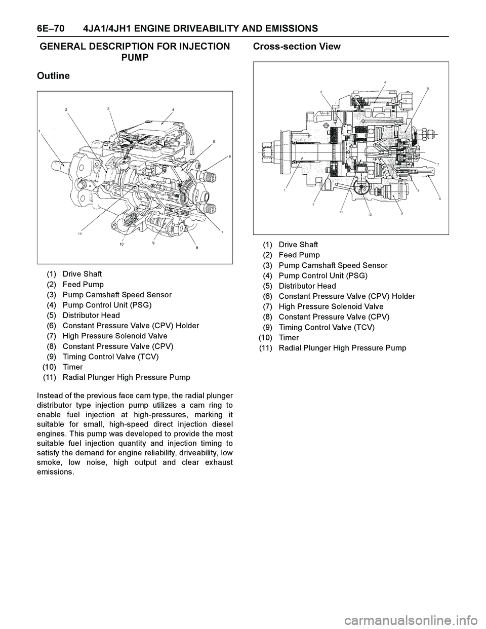
Outline
Instead of the previous face cam type, the radial plunger
distributor type injection pump utilizes a cam ring to
enable fuel injection at high-pressures, marking it
suitable for small, high-speed direct injection diesel
engines. This pump was developed to provide the most
suitable fuel injection quantity and injection timing to
satisfy the demand for engine reliability, driveability, low
smoke, low noise, high output and clear ex haust
emissions.
Cross-section View
(1) Drive Shaft
(2) Feed Pump
(3) Pump Camshaft Speed Sensor
(4) Pump Control Unit (PSG)
(5) Distributor Head
(6) Constant Pressure Valve (CPV) Holder
(7) High Pressure Solenoid Valve
(8) Constant Pressure Valve (CPV)
(9) Timing Control Valve (TCV)
(10) Timer
(11) Radial Plunger High Pressure Pump
(1) Drive Shaft
(2) Feed Pump
(3) Pump Camshaft Speed Sensor
(4) Pump Control Unit (PSG)
(5) Distributor Head
(6) Constant Pressure Valve (CPV) Holder
(7) High Pressure Solenoid Valve
(8) Constant Pressure Valve (CPV)
(9) Timing Control Valve (TCV)
(10) Timer
(11) Radial Plunger High Pressure Pump
Page 1452 of 4264
6E–80 4JA1/4JH1 ENGINE DRIVEABILITY AND EMISSIONS
Step 3: Simulate the symptom and isolate the
problem
Simulate the symptom and isolate the system by
reproducing all possible conditions suggested in Step 1
while monitoring suspected circuits/components/
systems to isolate the problem symptom. Begin with the
most logical circuit/component.
Isolate the circuit by dividing the suspect system into
simpler circuits. Nex t, confine the problem into a smaller
area of the system. Begin at the most logical point (or
point of easiest access) and thoroughly check the
isolated circuit for the fault, using basic circuit tests.
Hints
You can isolate a circuit by:
Unplugging connectors or removing a fuse to
separate one part of the circuit from another
If only component fails to operate, begin testing the
component
If a number of components do not operate, begin test
at areas of commonality (such as power sources,
ground circuits, switches, main connectors or major
components)
Substitute a known good part from the parts
department or the vehicle system
Try the suspect part in a known good vehicle
See Symptom Simulation Tests on the nex t page for
problem simulation procedures. Refer to service manual
sections 6E and 8A for information about intermittent
diagnosis. Follow procedures for basic circuit testing in
service manual section 8A.
What resources you should use
Whenever appropriate, you should use the following
resources to assist in the diagnostic process:
Service manual
Bulletins
Digital multimeter (with a MIN/MAX feature)
Tech II and Tech II upload function
Circuit testing tools (including connector kits/
harnesses and jumper wires)
Ex perience
Intermittent problem solving simulation methods
Customer complaint check sheet
Symptom Simulation Tests
1. Vibration
This method is useful when the customer complaint
analysis indicates that the problem occurs when the
vehicle/system undergoes some form of vibration.
For connectors and wire harness, slightly shake
vertically and horizontally. Inspect the connector joint
and body for damage. Also, tapping lightly along a
suspected circuit may be helpful.For parts and sensors, apply slight vibration to the part
with a light tap of the finger while monitoring the system
for a malfunction.
2. Heat
This method is important when the complaint suggests
that the problem occurs in a heated environment. Apply
moderate heat to the component with a hair drier or
similar tool while monitoring the system for a
malfunction.
CA UTION: Care must be take to avoid overheating
the component.
3. Water and Moisture
This method may be used when the complaint suggests
that the malfunction occurs on a rainy day or under
conditions of high humidity. In this case, apply water in a
light spray on the vehicle to duplicate the problem.
CA UTION: Care must be take to avoid directly
exposing electrical connections to water.
4. Electrical loads
This method involves turning systems ON (such as the
blower, lights or rear window defogger) to create a load
on the vehicle electrical system at the same time you
are monitoring the suspect circuit/component.
5e. Vehicle Operates as Designed
This condition refers to instances where a system
operating as designed is perceived to be unsatisfactory
or undesirable. In general, this is due to:
A lack of understanding by the customer
A conflict between customer ex pectations and
vehicle design intent
A system performance that is unacceptable to the
customer
What you should do
You can verify that a system is operating as designed
by:
Reviewing service manual functional/diagnostic
checks
Ex amining bulletins and other service information for
supplementary information
Compare system operation to an identical vehicle
If the condition is due to a customer misunderstanding
or a conflict between customer ex pectation and system
operation, you should ex plain the system operation to
the customer.
If the complaint is due to a case of unsatisfactory
system performance, you should contact Technical
Assistance for the latest information.
What resources you should use
Whenever possible, you should use the following
resources to facilitate the diagnostic process:
Page 1733 of 4264
4JA1/4JH1 ENGINE DRIVEABILITY AND EMISSIONS 6E–361
SYMPTOM DIAGNOSIS
PRELIMINARY CHECKS
Before using this section, perform the “On-Board
Diagnostic (OBD) System Check” and verify all of the
following items:
The engine control module (ECM) and check engine
lamp (MIL=malfunction indicator lamp are operating
correctly.
There are no Diagnostic Trouble Code(s) stored.
Tech 2 data is within normal operating range. Refer to
Typical Scan Data Values.
Verify the customer complaint and locate the correct
symptom in the table of contents. Perform the
procedure included in the symptom chart.
VISUAL/PHYSICAL CHECK
Several of the symptom procedures call for a careful
visual/physical check. This can lead to correcting a
problem without further checks and can save valuable
time. This check should include the following items:
ECM grounds for cleanliness, tightness and proper
location.
Vacuum hoses for splits, kinks, and proper
connection. Check thoroughly for any type of leak or
restriction.
Air intake ducts for collapsed or damaged areas.
Air leaks at throttle body mounting area, mass air flow
(MAF) sensor and intake manifold sealing surfaces.
Wiring for proper connections, pinches and cuts.
INTERMITTENT
Important: An intermittent problem may or may not turn
on the check engine lamp (MIL=malfunction indicator
lamp) or store a Diagnostic Trouble Code. Do NOT use
the Diagnostic Trouble Code (DTC) charts for
intermittent problems.
The fault must be present to locate the problem.
Most intermittent problems are cased by faulty electrical
connections or wiring. Perform a careful visual/physical
check for the following conditions.
Poor mating of the connector halves or a terminal not
fully seated in the connector (backed out).
Improperly formed or damaged terminal.
All connector terminals in the problem circuit should
be carefully checked for proper contact tension.
Poor terminal-to-wire connection. This requires
removing the terminal form the connector body to
check.
Check engine lamp (MIL=malfunction indicator lamp)
wire to ECM shorted to ground.
Poor ECM grounds. Refer to the ECM wiring
diagrams.Road test the vehicle with a Digital Multimeter
connected to a suspected circuit. An abnormal voltage
when the malfunction occurs is a good indication that
there is a fault in the circuit being monitored.
Using Tech 2 to help detect intermittent conditions. The
Tech 2 have several features that can be used to
located an intermittent condition. Use the following
features to find intermittent faults:
To check for loss of diagnostic code memory,
disconnect the MAF sensor and idle the engine until the
check engine lamp (MIL=malfunction indicator lamp)
comes on. Diagnostic Trouble Code P0100 should be
stored and kept in memory when the ignition is turned
OFF.
If not, the ECM is faulty. When this test is completed,
make sure that you clear the Diagnostic Trouble Code
P0100 from memory.
An intermittent check engine lamp (MIL=malfunction
indicator lamp) with no stored Diagnostic Trouble Code
may be caused by the following:
Check engine lamp (MIL=malfunction indicator lamp)
wire to ECM short to ground.
Poor ECM grounds. Refer to the ECM wiring
diagrams.
Check for improper installation of electrical options such
as light, cellular phones, etc. Check all wires from ECM
to the ignition control module for poor connections.
Check for an open diode across the A/C compressor
clutch and check for other open diodes (refer to wiring
diagrams in Electrical Diagnosis).
If problem has not been found, refer to ECM connector
symptom tables.
Check the “Broadcast Code” of the ECM, and
compare it with the latest Isuzu service bulletins and/
or Isuzu EEPROM reprogramming equipment to
determine if an update to the ECM's reprogrammable
memory has been released.
This identifies the contents of the reprogrammable
software and calibration contained in the ECM.
If the “Broadcast Code” is not the most current
available, it is advisable to reprogram the ECM's
EEPROM memory, which may either help identify a
hard-to find problem or may fix the problem.
The Service Programming System (SPS) will not allow
incorrect software programming or incorrect calibration
changes.
Page 1737 of 4264
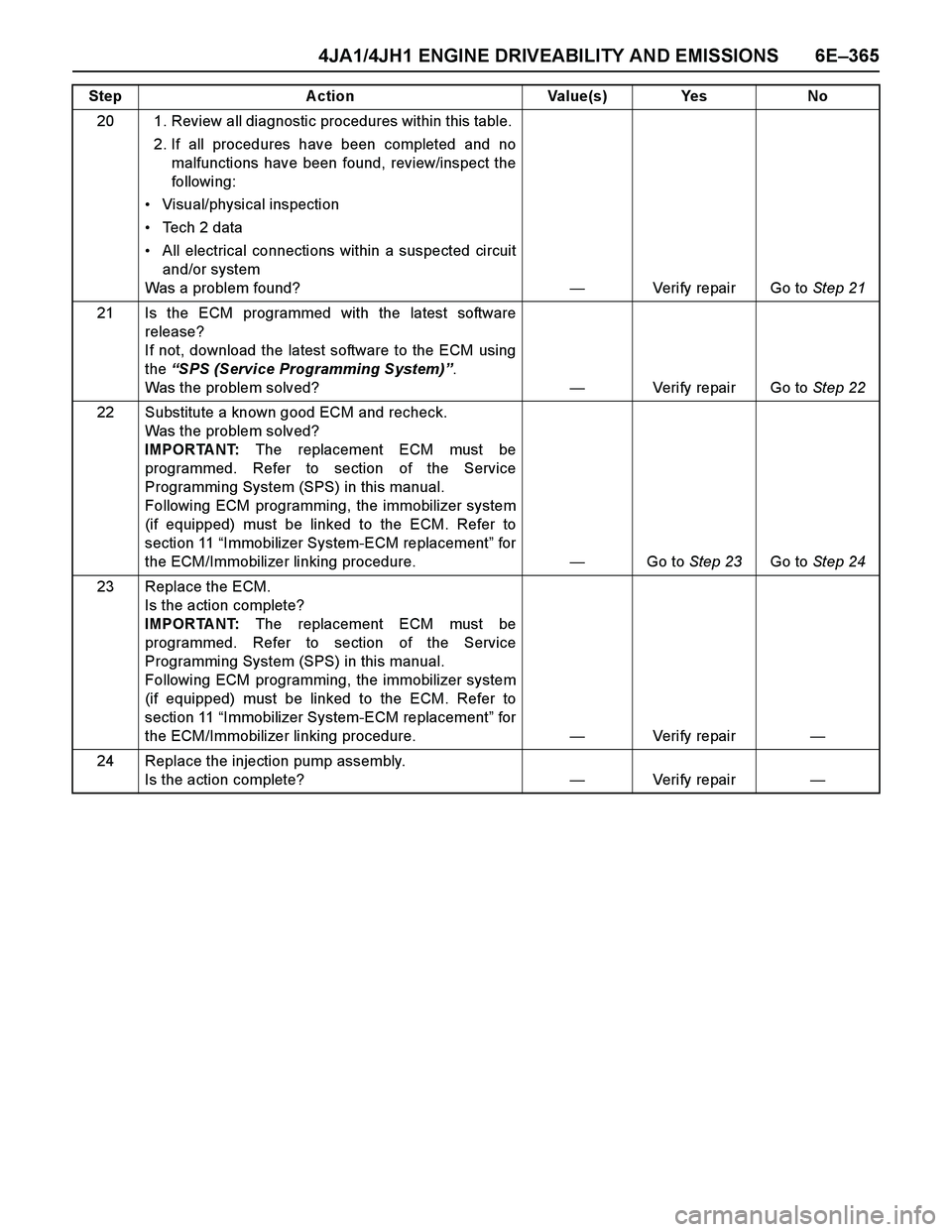
4JA1/4JH1 ENGINE DRIVEABILITY AND EMISSIONS 6E–365
20 1. Review all diagnostic procedures within this table.
2. If all procedures have been completed and no
malfunctions have been found, review/inspect the
followi ng:
Visual/physical inspection
Tech 2 data
All electrical connections within a suspected circuit
and/or system
Was a problem found?—Verify repair Go to Step 21
21 Is the ECM programmed with the latest software
release?
If not, download the latest software to the ECM using
the “SPS (Service Programming System)”.
Was the problem solved?—Verify repair Go to Step 22
22 Substitute a known good ECM and recheck.
Was the problem solved?
IMPORTANT: The replacement ECM must be
programmed. Refer to section of the Service
Programming System (SPS) in this manual.
Following ECM programming, the immobilizer system
(if equipped) must be linked to the ECM. Refer to
section 11 “Immobilizer System-ECM replacement” for
the ECM/Immobilizer linking procedure. —Go to Step 23Go to Step 24
23 Replace the ECM.
Is the action complete?
IMPORTANT: The replacement ECM must be
programmed. Refer to section of the Service
Programming System (SPS) in this manual.
Following ECM programming, the immobilizer system
(if equipped) must be linked to the ECM. Refer to
section 11 “Immobilizer System-ECM replacement” for
the ECM/Immobilizer linking procedure.—Veri fy repai r—
24 Replace the injection pump assembly.
Is the action complete?—Veri fy repai r— Step Action Value(s) Yes No
Page 1741 of 4264
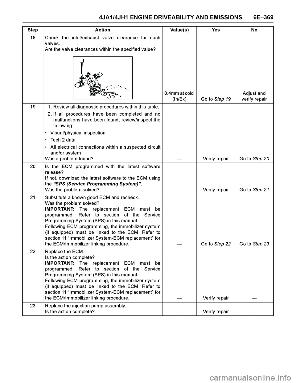
4JA1/4JH1 ENGINE DRIVEABILITY AND EMISSIONS 6E–369
18 Check the inlet/ex haust valve clearance for each
valves.
Are the valve clearances within the specified value?
0.4mm at cold
(In/Ex ) Go to Step 19Adjust and
verify repair
19 1. Review all diagnostic procedures within this table.
2. If all procedures have been completed and no
malfunctions have been found, review/inspect the
followi ng:
Visual/physical inspection
Tech 2 data
All electrical connections within a suspected circuit
and/or system
Was a problem found?—Verify repair Go to Step 20
20 Is the ECM programmed with the latest software
release?
If not, download the latest software to the ECM using
the “SPS (Service Programming System)”.
Was the problem solved?—Verify repair Go to Step 21
21 Substitute a known good ECM and recheck.
Was the problem solved?
IMPORTANT: The replacement ECM must be
programmed. Refer to section of the Service
Programming System (SPS) in this manual.
Following ECM programming, the immobilizer system
(if equipped) must be linked to the ECM. Refer to
section 11 “Immobilizer System-ECM replacement” for
the ECM/Immobilizer linking procedure. —Go to Step 22Go to Step 23
22 Replace the ECM.
Is the action complete?
IMPORTANT: The replacement ECM must be
programmed. Refer to section of the Service
Programming System (SPS) in this manual.
Following ECM programming, the immobilizer system
(if equipped) must be linked to the ECM. Refer to
section 11 “Immobilizer System-ECM replacement” for
the ECM/Immobilizer linking procedure.—Veri fy repai r—
23 Replace the injection pump assembly.
Is the action complete?—Veri fy repai r— Step Action Value(s) Yes No
Page 1748 of 4264
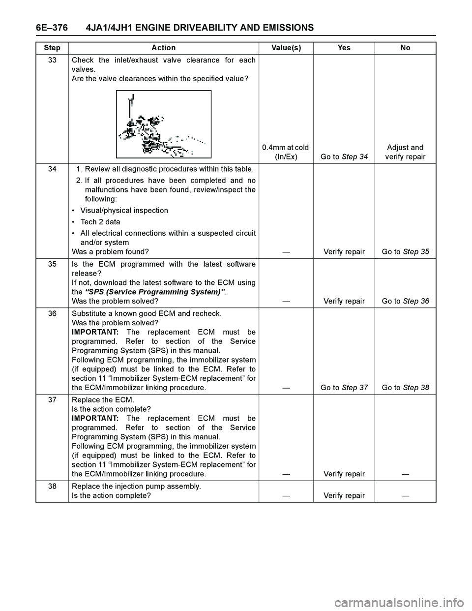
6E–376 4JA1/4JH1 ENGINE DRIVEABILITY AND EMISSIONS
33 Check the inlet/ex haust valve clearance for each
valves.
Are the valve clearances within the specified value?
0.4mm at cold
(In/Ex ) Go to Step 34Adjust and
verify repair
34 1. Review all diagnostic procedures within this table.
2. If all procedures have been completed and no
malfunctions have been found, review/inspect the
followi ng:
Visual/physical inspection
Tech 2 data
All electrical connections within a suspected circuit
and/or system
Was a problem found?—Verify repair Go to Step 35
35 Is the ECM programmed with the latest software
release?
If not, download the latest software to the ECM using
the “SPS (Service Programming System)”.
Was the problem solved?—Verify repair Go to Step 36
36 Substitute a known good ECM and recheck.
Was the problem solved?
IMPORTANT: The replacement ECM must be
programmed. Refer to section of the Service
Programming System (SPS) in this manual.
Following ECM programming, the immobilizer system
(if equipped) must be linked to the ECM. Refer to
section 11 “Immobilizer System-ECM replacement” for
the ECM/Immobilizer linking procedure. —Go to Step 37Go to Step 38
37 Replace the ECM.
Is the action complete?
IMPORTANT: The replacement ECM must be
programmed. Refer to section of the Service
Programming System (SPS) in this manual.
Following ECM programming, the immobilizer system
(if equipped) must be linked to the ECM. Refer to
section 11 “Immobilizer System-ECM replacement” for
the ECM/Immobilizer linking procedure.—Veri fy repai r—
38 Replace the injection pump assembly.
Is the action complete?—Veri fy repai r— Step Action Value(s) Yes No
Page 1753 of 4264
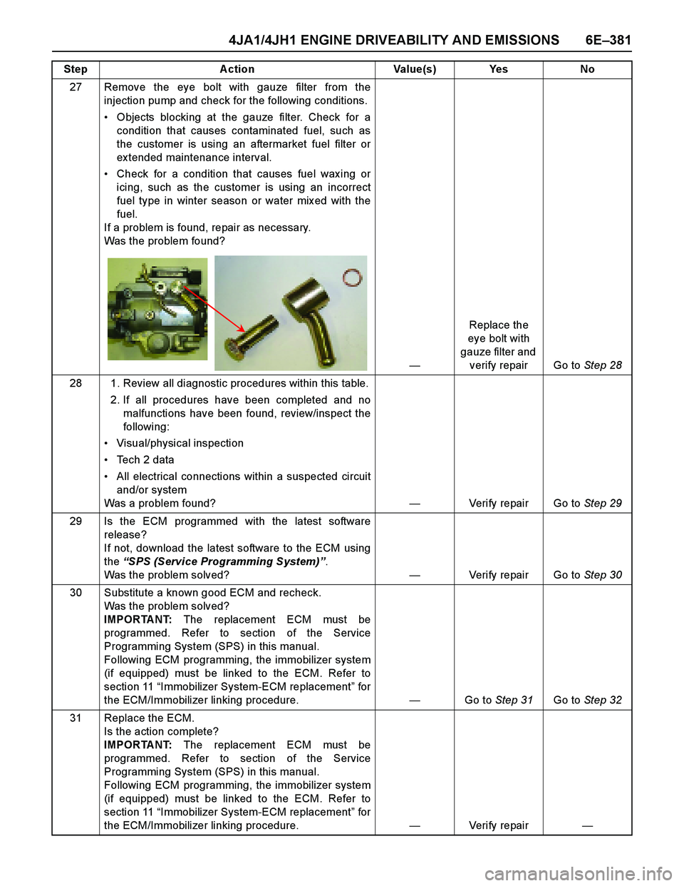
4JA1/4JH1 ENGINE DRIVEABILITY AND EMISSIONS 6E–381
27 Remove the eye bolt with gauze filter from the
injection pump and check for the following conditions.
Objects blocking at the gauze filter. Check for a
condition that causes contaminated fuel, such as
the customer is using an aftermarket fuel filter or
ex tended maintenance interval.
Check for a condition that causes fuel wax ing or
icing, such as the customer is using an incorrect
fuel type in winter season or water mix ed with the
fuel.
If a problem is found, repair as necessary.
Was the problem found?
—Replace the
eye bolt with
gauze filter and
verify repair Go to Step 28
28 1. Review all diagnostic procedures within this table.
2. If all procedures have been completed and no
malfunctions have been found, review/inspect the
followi ng:
Visual/physical inspection
Tech 2 data
All electrical connections within a suspected circuit
and/or system
Was a problem found?—Verify repair Go to Step 29
29 Is the ECM programmed with the latest software
release?
If not, download the latest software to the ECM using
the “SPS (Service Programming System)”.
Was the problem solved?—Verify repair Go to Step 30
30 Substitute a known good ECM and recheck.
Was the problem solved?
IMPORTANT: The replacement ECM must be
programmed. Refer to section of the Service
Programming System (SPS) in this manual.
Following ECM programming, the immobilizer system
(if equipped) must be linked to the ECM. Refer to
section 11 “Immobilizer System-ECM replacement” for
the ECM/Immobilizer linking procedure. —Go to Step 31Go to Step 32
31 Replace the ECM.
Is the action complete?
IMPORTANT: The replacement ECM must be
programmed. Refer to section of the Service
Programming System (SPS) in this manual.
Following ECM programming, the immobilizer system
(if equipped) must be linked to the ECM. Refer to
section 11 “Immobilizer System-ECM replacement” for
the ECM/Immobilizer linking procedure.—Veri fy repai r— Step Action Value(s) Yes No