Page 3671 of 4264
TRANSFER CONTROL SYSTEM 7D1-45
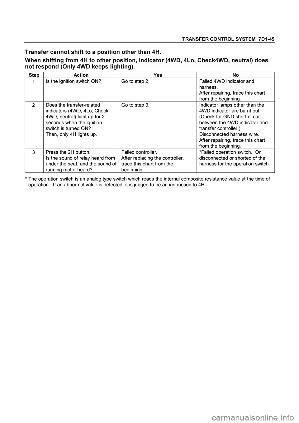
Transfer cannot shift to a position other than 4H.
When shifting from 4H to other position, indicator (4WD, 4Lo, Check4WD, neutral) does
not respond (Only 4WD keeps lighting).
Step Action Yes No
1 Is the ignition switch ON? Go to step 2. Failed 4WD indicator and
harness.
After repairing, trace this chart
from the beginning.
2 Does the transfer-related
indicators (4WD, 4Lo, Check
4WD, neutral) light up for 2
seconds when the ignition
switch is turned ON?
Then, only 4H lights up. Go to step 3. Indicator lamps other than the
4WD indicator are burnt out.
(Check for GND short circuit
between the 4WD indicator and
transfer controller.)
Disconnected harness wire.
After repairing, trace this chart
from the beginning.
3 Press the 2H button.
Is the sound of relay heard from
under the seat, and the sound of
running motor heard? Failed controller.
After replacing the controller,
trace this chart from the
beginning. *Failed operation switch. Or
disconnected or shorted of the
harness for the operation switch.
* The operation switch is an analog type switch which reads the internal composite resistance value at the time of
operation. If an abnormal value is detected, it is judged to be an instruction to 4H.
Page 3673 of 4264
TRANSFER CONTROL SYSTEM 7D1-47
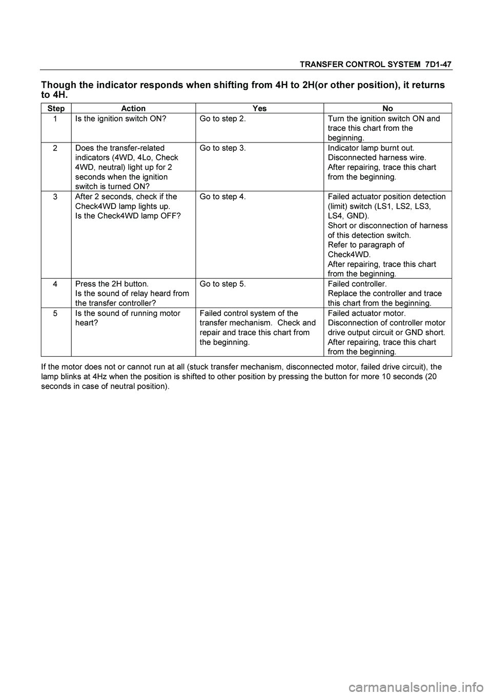
Though the indicator responds when shifting from 4H to 2H(or other position), it returns
to 4H.
Step Action Yes No
1 Is the ignition switch ON? Go to step 2. Turn the ignition switch ON and
trace this chart from the
beginning.
2 Does the transfer-related
indicators (4WD, 4Lo, Check
4WD, neutral) light up for 2
seconds when the ignition
switch is turned ON? Go to step 3. Indicator lamp burnt out.
Disconnected harness wire.
After repairing, trace this chart
from the beginning.
3 After 2 seconds, check if the
Check4WD lamp lights up.
Is the Check4WD lamp OFF? Go to step 4. Failed actuator position detection
(limit) switch (LS1, LS2, LS3,
LS4, GND).
Short or disconnection of harness
of this detection switch.
Refer to paragraph of
Check4WD.
After repairing, trace this chart
from the beginning.
4 Press the 2H button.
Is the sound of relay heard from
the transfer controller? Go to step 5. Failed controller.
Replace the controller and trace
this chart from the beginning.
5 Is the sound of running motor
heart? Failed control system of the
transfer mechanism. Check and
repair and trace this chart from
the beginning. Failed actuator motor.
Disconnection of controller motor
drive output circuit or GND short.
After repairing, trace this chart
from the beginning.
If the motor does not or cannot run at all (stuck transfer mechanism, disconnected motor, failed drive circuit), the
lamp blinks at 4Hz when the position is shifted to other position by pressing the button for more 10 seconds (20
seconds in case of neutral position).
Page 3691 of 4264
TRANSMISSION CONTROL SYSTEM (AW30 –40LE) (V6 3.5L) 7A2-11
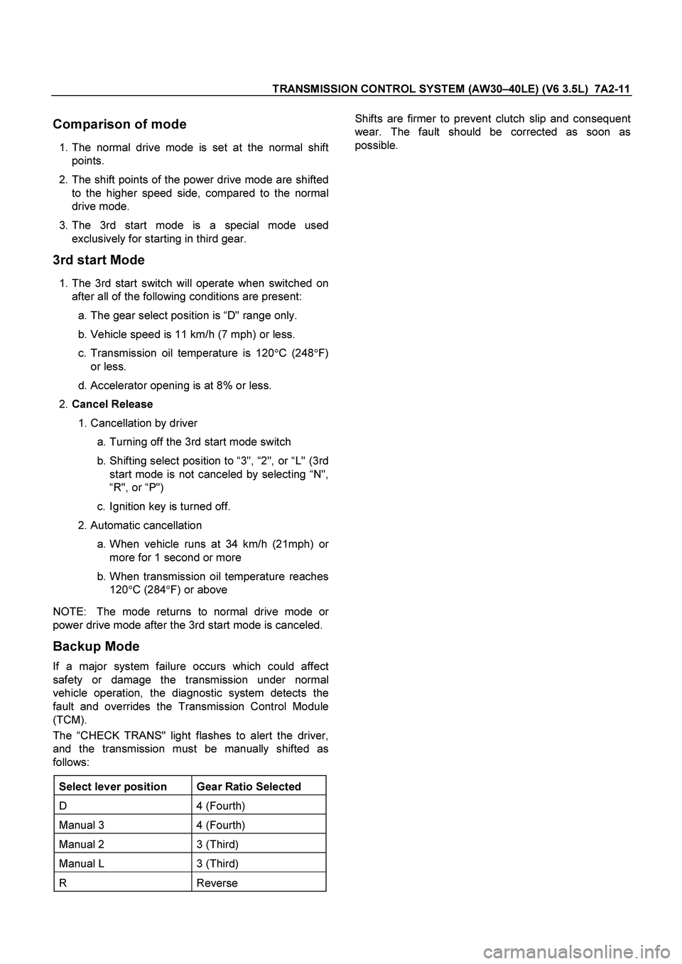
Comparison of mode
1. The normal drive mode is set at the normal shift
points.
2. The shift points of the power drive mode are shifted
to the higher speed side, compared to the normal
drive mode.
3. The 3rd start mode is a special mode used
exclusively for starting in third gear.
3rd start Mode
1. The 3rd start switch will operate when switched on
after all of the following conditions are present:
a. The gear select position is “D" range only.
b. Vehicle speed is 11 km/h (7 mph) or less.
c. Transmission oil temperature is 120 �
C (248 �
F)
or less.
d. Accelerator opening is at 8% or less.
2. Cancel Release
1. Cancellation by driver
a. Turning off the 3rd start mode switch
b. Shifting select position to “3", “2", or “L" (3rd
start mode is not canceled by selecting “N",
“ R", or “P")
c. Ignition key is turned off.
2. Automatic cancellation
a. When vehicle runs at 34 km/h (21mph) o
r
more for 1 second or more
b. When transmission oil temperature reaches 120 �
C (284 �
F) or above
NOTE: The mode returns to normal drive mode o
r
power drive mode after the 3rd start mode is canceled.
Backup Mode
If a major system failure occurs which could affect
safety or damage the transmission under normal
vehicle operation, the diagnostic system detects the
fault and overrides the Transmission Control Module
(TCM).
The “CHECK TRANS" light flashes to alert the driver,
and the transmission must be manually shifted as
follows:
Select lever position Gear Ratio Selected
D 4 (Fourth)
Manual 3 4 (Fourth)
Manual 2 3 (Third)
Manual L 3 (Third)
R Reverse
Shifts are firmer to prevent clutch slip and consequent
wear. The fault should be corrected as soon as
possible.
Page 3692 of 4264
7A2-12 TRANSMISSION CONTROL SYSTEM (AW30 –40LE) (V6 3.5L)
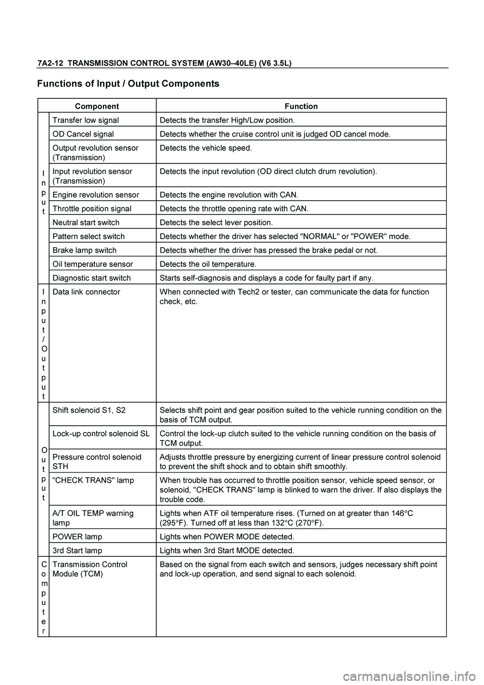
Functions of Input / Output Components
Component Function
Transfer low signal Detects the transfer High/Low position.
OD Cancel signal Detects whether the cruise control unit is judged OD cancel mode.
Output revolution sensor
(Transmission) Detects the vehicle speed.
Input revolution sensor
(Transmission) Detects the input revolution (OD direct clutch drum revolution).
Engine revolution sensor Detects the engine revolution with CAN.
Throttle position signal Detects the throttle opening rate with CAN.
Neutral start switch Detects the select lever position.
Pattern select switch Detects whether the driver has selected "NORMAL" or "POWER" mode.
Brake lamp switch Detects whether the driver has pressed the brake pedal or not.
Oil temperature sensor Detects the oil temperature.
I
n
p
u t
Diagnostic start switch Starts self-diagnosis and displays a code for faulty part if any.
I
n
p
u t
/
O
u t
p
u t Data link connector When connected with Tech2 or tester, can communicate the data for function
check, etc.
Shift solenoid S1, S2 Selects shift point and gear position suited to the vehicle running condition on the
basis of TCM output.
Lock-up control solenoid SL Control the lock-up clutch suited to the vehicle running condition on the basis of TCM output.
Pressure control solenoid
STH Adjusts throttle pressure by energizing current of linear pressure control solenoid
to prevent the shift shock and to obtain shift smoothly.
"CHECK TRANS" lamp When trouble has occurred to throttle position sensor, vehicle speed sensor, or
solenoid, "CHECK TRANS" lamp is blinked to warn the driver. If also displays the
trouble code.
A/T OIL TEMP warning
lamp Lights when ATF oil temperature rises. (Turned on at greater than 146
�
C
(295 �
F). Turned off at less than 132 �
C (270 �
F).
POWER lamp Lights when POWER MODE detected.
O
u
t
p
u
t
3rd Start lamp Lights when 3rd Start MODE detected.
C
o
m
p
u t
e r Transmission Control
Module (TCM) Based on the signal from each switch and sensors, judges necessary shift point
and lock-up operation, and send signal to each solenoid.
Page 3700 of 4264
7A2-20 TRANSMISSION CONTROL SYSTEM (AW30 –40LE) (V6 3.5L)
RTW37ALH000101
Once the test vehicle has been identified an
“ Application (Powertrain) Menu" screen appears.
Please select the appropriate application.
The following table shows, which functions are used fo
r
the available equipment versions.
F0: Diagnostic Trouble Codes
F0: Read DTC Info As stored By ECU
F1: Clear DTC Information
F2: DTC Information
F1: Data Display
F2: Snap Shot
F3: Miscllaneous Tests
F0: Lamps
F0: Power Lamp Test
F1: 3rd start Lamp Test
F2: AT Oil Temperature Lamp
F3: Check Light
F1: Solenoids
F0: Shift solenoid A (S1)
F1: Shift Solenoid B (S2)
F2: Pressure Control Solenoid (PCS)
Page 3702 of 4264
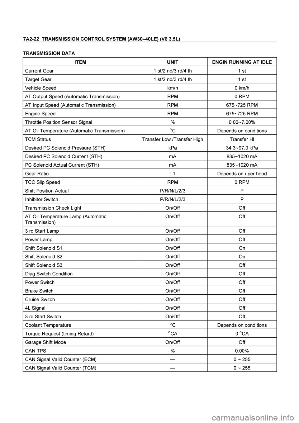
7A2-22 TRANSMISSION CONTROL SYSTEM (AW30 –40LE) (V6 3.5L)
TRANSMISSION DATA
ITEM UNIT ENGIN RUNNING AT IDLE
Current Gear 1 st/2 nd/3 rd/4 th 1 st
Target Gear 1 st/2 nd/3 rd/4 th 1 st
Vehicle Speed km/h 0 km/h
AT Output Speed (Automatic Transmission) RPM 0 RPM
AT Input Speed (Automatic Transmission) RPM 675�725 RPM
Engine Speed RPM 675�725 RPM
Throttle Position Sensor Signal % 0.00�7.00%
AT Oil Temperature (Automatic Transmission) �C Depends on conditions
TCM Status Transfer Low /Transfer High Transfer HI
Desired PC Solenoid Pressure (STH) kPa 34.3�97.0 kPa
Desired PC Solenoid Current (STH) mA 835�1020 mA
PC Solenoid Actual Current (STH) mA 835�1020 mA
Gear Ratio : 1 Depends on uper hood
TCC Slip Speed RPM 0 RPM
Shift Position Actual P/R/N/L/2/3 P
Inhibitor Switch P/R/N/L/2/3 P
Transmission Check Light On/Off Off
AT Oil Temperature Lamp (Automatic
Transmission) On/Off Off
3 rd Start Lamp On/Off Off
Power Lamp On/Off Off
Shift Solenoid S1 On/Off On
Shift Solenoid S2 On/Off On
Shift Solenoid S3 On/Off Off
Diag Switch Condition On/Off Off
Power Switch On/Off Off
Brake Switch On/Off Off
Cruise Switch On/Off Off
4L Signal On/Off Off
3 rd Start Switch On/Off Off
Coolant Temperature �C Depends on conditions
Torque Request (timing Retard) �CA 0 �CA
Garage Shift Mode On/Off Off
CAN TPS % 0.00%
CAN Signal Valid Counter (ECM)
— 0 � 255
CAN Signal Valid Counter (TCM) — 0 � 255
Page 3716 of 4264
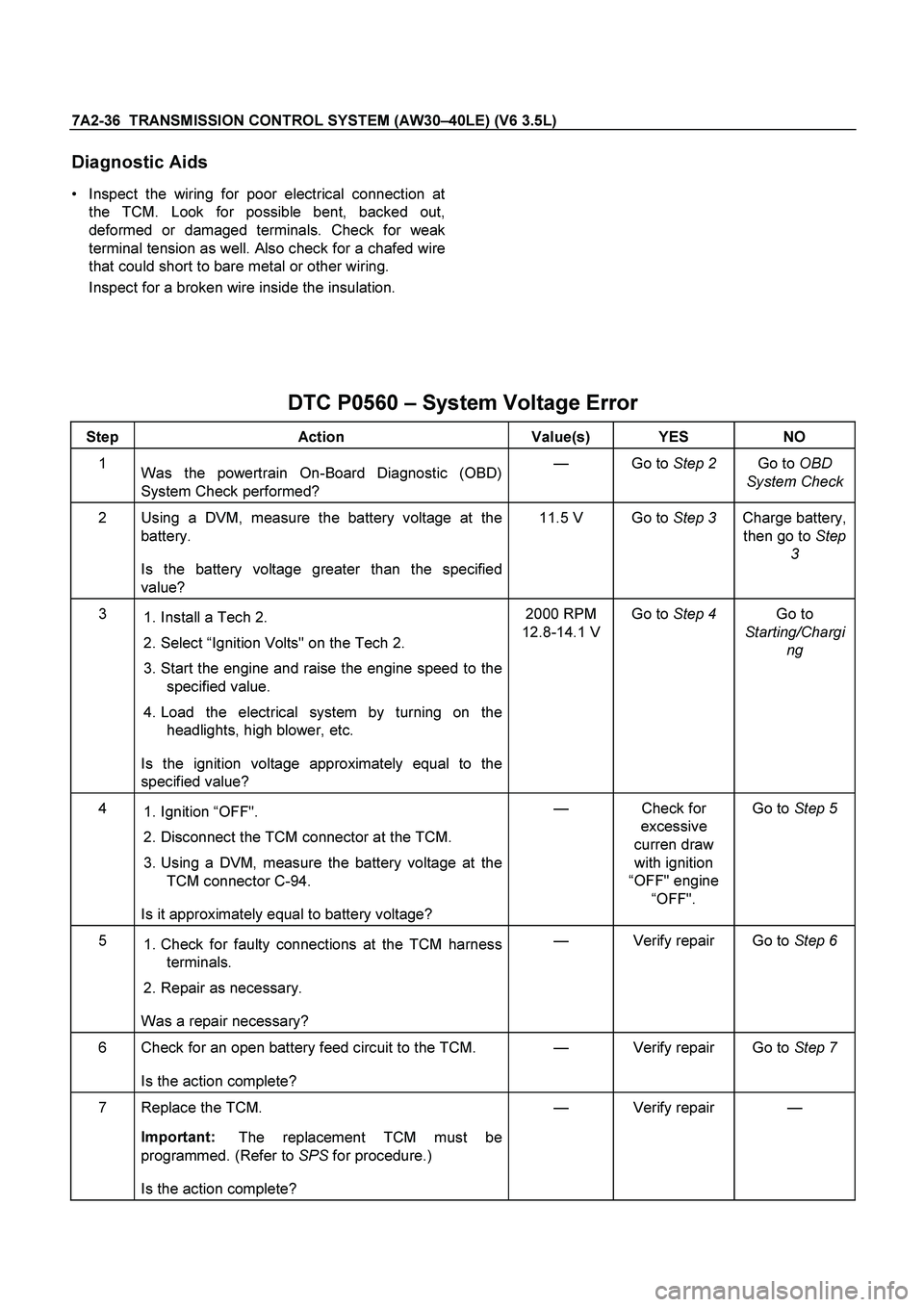
7A2-36 TRANSMISSION CONTROL SYSTEM (AW30–40LE) (V6 3.5L)
Diagnostic Aids
Inspect the wiring for poor electrical connection at
the TCM. Look for possible bent, backed out,
deformed or damaged terminals. Check for weak
terminal tension as well. Also check for a chafed wire
that could short to bare metal or other wiring.
Inspect for a broken wire inside the insulation.
DTC P0560 – System Voltage Error
Step Action Value(s) YES NO
1
Was the powertrain On-Board Diagnostic (OBD)
System Check performed? — Go to Step 2 Go to OBD
System Check
2 Using a DVM, measure the battery voltage at the
battery.
Is the battery voltage greater than the specified
value? 11.5 V Go to Step 3 Charge battery,
then go to Step
3
3
1. Install a Tech 2.
2. Select “Ignition Volts" on the Tech 2.
3. Start the engine and raise the engine speed to the
specified value.
4. Load the electrical system by turning on the
headlights, high blower, etc.
Is the ignition voltage approximately equal to the
specified value? 2000 RPM
12.8-14.1 VGo to Step 4 Go to
Starting/Chargi
ng
4
1. Ignition “OFF".
2. Disconnect the TCM connector at the TCM.
3. Using a DVM, measure the battery voltage at the
TCM connector C-94.
Is it approximately equal to battery voltage? — Check for
excessive
curren draw
with ignition
“OFF" engine
“OFF". Go to Step 5
5
1. Check for faulty connections at the TCM harness
terminals.
2. Repair as necessary.
Was a repair necessary? — Verify repair Go to Step 6
6 Check for an open battery feed circuit to the TCM.
Is the action complete? — Verify repair Go to Step 7
7 Replace the TCM.
Important:
The replacement TCM must be
programmed. (Refer to SPS for procedure.)
Is the action complete? — Verify repair —
Page 3780 of 4264
7A3-24 ON-VEHICLE SERVICE (AW30 –40LE)
Brake Signal
Inspection
Check that the brake light comes on when the brake
pedal is depressed.
310RW020