Page 3033 of 4264
HEATER AND AIR CONDITIONING 1-23
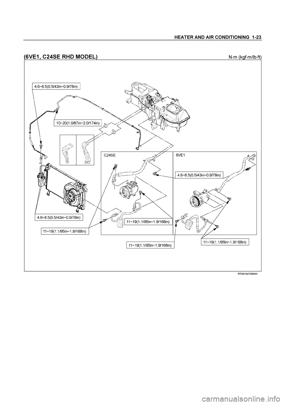
(6VE1, C24SE RHD MODEL) N�m (kgf�m/lb�ft)
RTW410LF000401
Page 3035 of 4264
HEATER AND AIR CONDITIONING 1-25
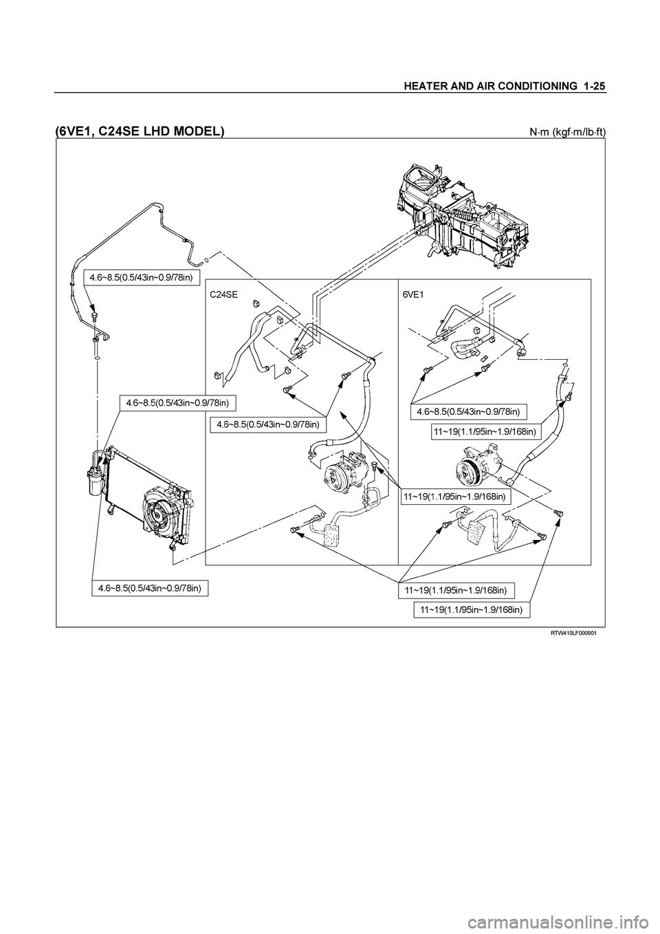
(6VE1, C24SE LHD MODEL) N�m (kgf�m/lb�ft)
RTW410LF000901
Page 3054 of 4264
1-44 HEATER AND AIR CONDITIONING
REMOVAL AND INSTALLATION (C24SE)
RTW310MF000401
Removal Steps
1. Magnetic clutch harness connector
2. Compressor belt
3. Refrigerant line
4. Bolt; compressor to bracket
5. Compressor assembly
Installation Steps
5. Compressor assembly
� 4. Bolt; compressor to bracket
� 3. Refrigerant line
� 2. Compressor belt
1. Magnetic clutch harness connector
Page 3287 of 4264

IMMOBILIZER SYSTEM 11A-1
SECTION 11A
IMMOBILIZER SYSTEM
CONTENTS
Service Precaution.................................................
11A-2
General Description...............................................
11A-3
What happens without proper transponder
operation? ..........................................................
11A-6
No proper transponder is available, what
should be done for the system? ......................
11A-6
Caution to the operation.....................................
11A-6
Summary of operation........................................
11A-6
What your organization should provide for
your customer ....................................................
11A-6
Car Pass .............................................................
11A-6
Security code management ..............................
11A-6
Essential tool (Scan tool : Tech-2) ..................
11A-6
Circuit Diagram .................................................
11A-7
Parts Location.........................................................
11A-10
Immobilizer control unit (ICU); For Electronic
Control Engine (6VE1, C24SE, 4JH1-TC,
4JA1-TC) .......................................................... 11A-11
Pin-outs; For Electronic Control Engine
(6VE1, C24SE, 4JH1-TC, 4JA1-TC)...............
11A-12
Immobilizer control unit (ICU); Mechanical
Control Engine (4JA1-T) .................................. 11A-13
Immobilizer coil (Antenna) ...................................
11A-15
Transponder (Key) ............................................ 11A-15
Immobilizer warning lamp ................................. 11A-15
Engine control module (ECM) .......................... 11A-15
Car Pass Card .................................................. 11A-16
Loss of car pass card.........................................
11A-16
Instructions on Filling Out the form "Data
request, car pass" .............................................
11A-16
Important Instructions ........................................
11A-17
lmportant information on Programming .............
11A-19
Security code ......................................................
11A-19
Entering a code ..................................................
11A-19
Transponder (Key) .............................................
11A-19
Important .............................................................
11A-19
Tech-2 Scan Tool ..................................................
11A-20
Tech-2 Features .................................................
11A-21
Getting Started ...................................................
11A-21
Operating Procedure .........................................
11A-22
Menu ....................................................................
11A-23
DTC ......................................................................
11A-23
Clear DTC Information .......................................
11A-23
Tech-2 Data Display ...........................................
11A-23
Check Vehicle Identification Number (VIN) ....
11A-23
Reset Immobilizer (Reset Immobilizer
Control Unit) .......................................................
11A-23
Reset Engine Control Module (Reset ECM) ...
11A-24
Erase transponder key .......................................
11A-24
Programming Immobilizer Function .................
11A-25
Programming ICU ...............................................
11A-26
Programming ECM .............................................
11A-27
Programming ICU and ECM .............................
11A-28
Transponder program ........................................
11A-28
Data List ...............................................................
11A-30
Diagnostic procedure ............................................
11A-31
Clearing Diagnostic Trouble Codes ....................
11A-31
Verifying Vehicle Repair ........................................
11A-31
Diagnostic Aids ......................................................
11A-31
Check the condition for system parts ..............
11A-31
Check the Electro-Magnetic Interference
(EMI) ....................................................................
11A-31
Check the other items ........................................
11A-31
Check the operation ...........................................
11A-31
Diagnostic Trouble Code (DTC) list ....................
11A-32
IMMOBILIZER SYSTEM CHECK ........................
11A-33
NO IMMOBILIZER WARNING LAMP .................
11A-36
IMMOBILIZER WARNING LAMP ON STEADY 11A-37
B0001 REPLACE ELECTRONIC CONTROL
UNIT (ECU) (IMMOBILIZER FAULT) ................
11A-38
B0002 IMMOBILIZER NOT PROGRAMMED ....
11A-39
B0003 TRANSPONDER KEY PROBLEM ..........
11A-40
B0004 IMMOBILIZER COIL CIRCUIT
(ANTENNA COIL FAULT) ...................................
11A-42
B0005 COMMUNICATION LINE W VOLTAGE
LOW .......................................................................
11A-43
B0006 COMMUNICATION LINE W VOLTAGE
HIGH .......................................................................
11A-44
B0007 NO ENGINE REQUEST RECEIVED ......
11A-45
B0008 WRONG TRANSPONDER KEY .............
11A-47
B0009 NO TRANSPONDER KEY
PROGRAMMED ...................................................
11A-48
Page 3289 of 4264
IMMOBILIZER SYSTEM 11A-3
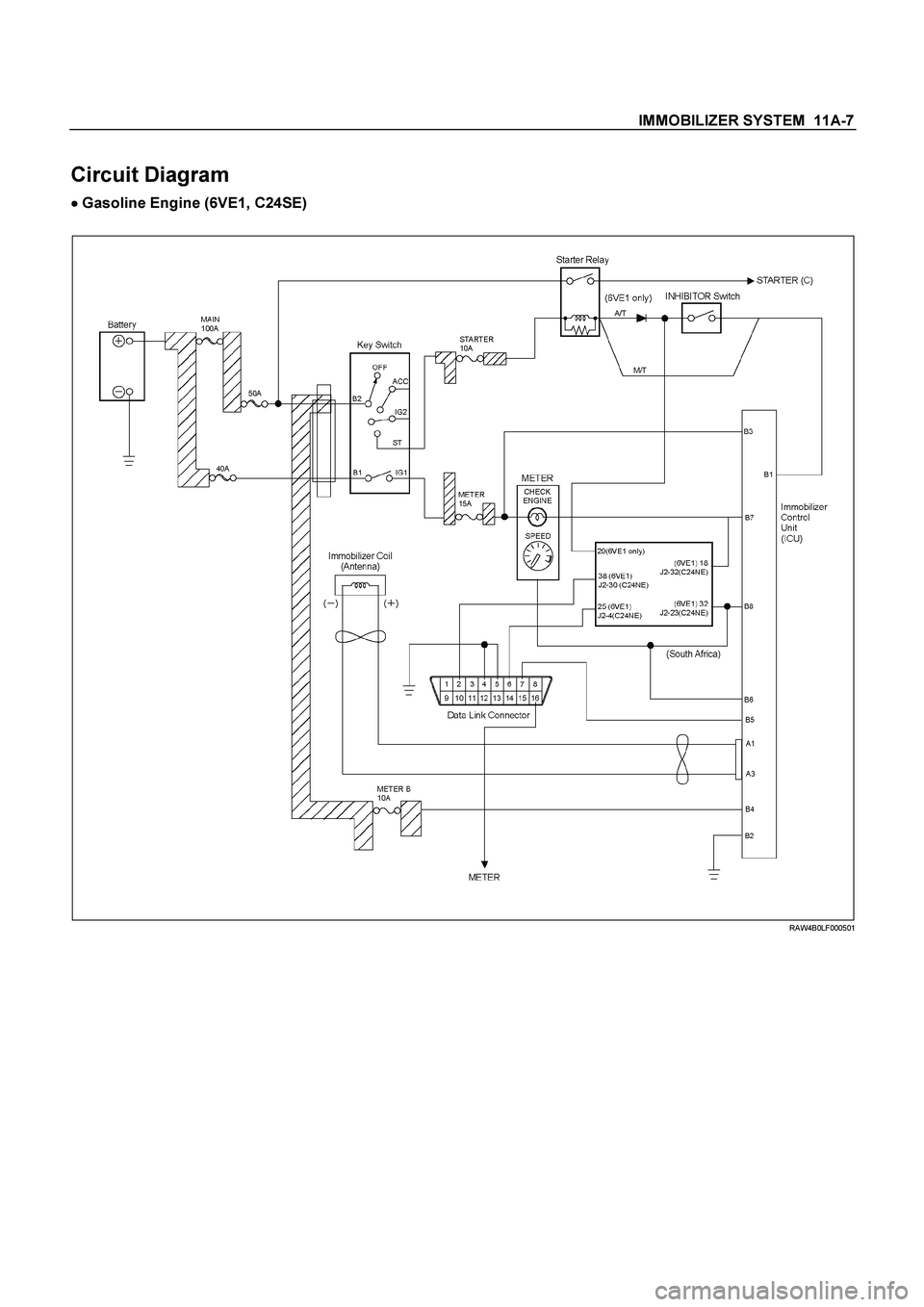
General Description
The immobilizer system consists of the four major
components which are Engine Control Module (ECM),
Immobilizer Control Unit (lCU), transponder, and scan
tool (Tech-2).
This system can be activated by a correctly programmed
transponder and starter switch is set to OFF.
This system can be deactivated by a correctl
y
programmed transponder key connected with a correctly
programmed ECM and a correctly programmed lCU.
While the system is on :
The starter cut off relay deactivates function of starter,
and the fuel injector power source is deactivated also.
�
Check Engine lamp is flashing.
�
Warning buzzer is operating.
(With antitheft system)
�
�� � Gasoline Engine (6VE1, C24SE)
LTW3BALF000101
Page 3293 of 4264
IMMOBILIZER SYSTEM 11A-7
Circuit Diagram
�
�� � Gasoline Engine (6VE1, C24SE)
RAW4B0LF000501
Page 3297 of 4264
IMMOBILIZER SYSTEM 11A-11
Immobilizer control unit (ICU); For
Electronic Control Engine (6VE1,
C24SE, 4JH1-TC, 4JA1-TC)
Immobilizer control unit (ICU) permits engine starting,
when the security code which compares the securit
y
code registered into the transponder (key) and the
security code registered into ICU, and is similarl
y
registered into ICU and engine control unit (ECM) is
compared and it is judged that it is normal. When the
code registered into the key is unusual, and when not
recognizing a security code, ICU does not permit
starting of engine.
RUW38HSF000101
Page 3298 of 4264
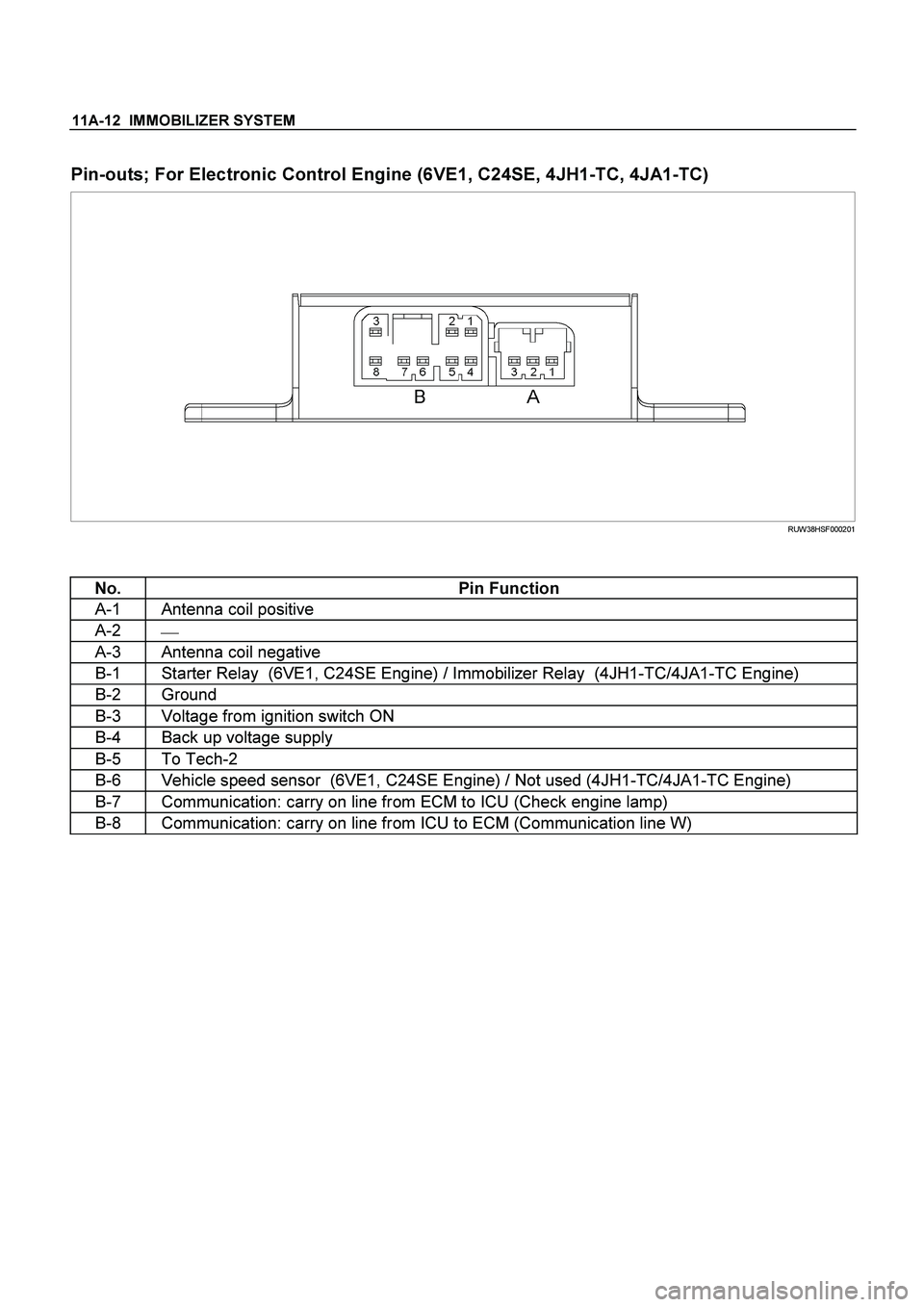
11A-12 IMMOBILIZER SYSTEM
Pin-outs; For Electronic Control Engine (6VE1, C24SE, 4JH1-TC, 4JA1-TC)
RUW38HSF000201
No. Pin Function
A-1 Antenna coil positive
A-2
�
A-3 Antenna coil negative
B-1 Starter Relay (6VE1, C24SE Engine) / Immobilizer Relay (4JH1-TC/4JA1-TC Engine)
B-2 Ground
B-3 Voltage from ignition switch ON
B-4 Back up voltage supply
B-5 To Tech-2
B-6 Vehicle speed sensor (6VE1, C24SE Engine) / Not used (4JH1-TC/4JA1-TC Engine)
B-7 Communication: carry on line from ECM to ICU (Check engine lamp)
B-8 Communication: carry on line from ICU to ECM (Communication line W)

RTW310MF000401
Removal Steps
1. Magnetic clutch harness connector
2. Compressor belt
3. Refrigerant line")
,
Immobilizer Control Unit (lCU), transponder, and s")
; For
Electronic Control Engine (6VE1,
C24SE, 4JH1-TC, 4JA1-TC)
Immobilizer control unit (ICU) permits engine starting,
when the security")