Page 2540 of 4264
6C-16 ENGINE FUEL (C24SE)
Fuel Filler Cap
General Description
A vacuum valve and pressure valve are built into the
fuel filler cap which adjusts the fuel pressure in the fuel
tank to prevent fuel tank damage.
RTW36CSH000401
Legend
(1) Pressure Valve
(2) Vacuum Valve
(3) Seal Ring
Inspection
The fuel filler cap must be inspected for seal condition.
The fuel filler cap must be replaced if found defective
CAUTION: A replacement fuel filler cap must be the
same as the original. The fuel filler cap valve was
designed primarily for this application and must be
replaced with the same type or decreased engine
performance may occur.
Page 2541 of 4264
ENGINE FUEL (C24SE) 6C-17
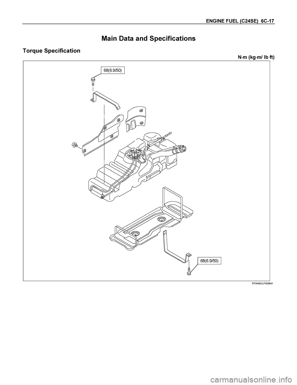
Main Data and Specifications
Torque Specification
N�
�� �m (kg�
�� �m/ lb ft)
RTW46CLF000601
Page 2542 of 4264
6C-18 ENGINE FUEL (C24SE)
Special Tools
ILLUSTRATION PART NO.
PART NAME
5–8840–2602–0
(J–39765)
Remover; fuel pump
retainer
Page 2577 of 4264
 .......................")
ENGINE DRIVEABILITY AND EMISSIONS 6E–1
ENGINE
CONTENTS
C24SE ENGINE DRIVEABILITY AND EMISSIONS
ABBREVIATIONS CHARTS ......................... 6E-6
ECM Circuit Diagram (1/2) ............................ 6E-11
ECM Circuit Diagram (2/2) ............................ 6E-12
GROUND POINT CHART - LHD G.EXP (1/4) 6E-13
GROUND POINT CHART - RHD G.EXP (1/4) 6E-17
LOCATION ................................................... 6E-21
CABLE HARNESS & CONNECTOR
LOCATION .............................................. 6E-23
CABLE HARNESS & CONNECTOR
LOCATION � LHD ................................... 6E-24
CABLE HARNESS & CONNECTOR
LOCATION � RHD ................................... 6E-25
CONNECTOR LIST ...................................... 6E-28
RELAY AND FUSE ....................................... 6E-30
RELAY AND FUSE BOX LOCATION
(LHD & RHD) ........................................... 6E-30
FUSE AND RELAY LOCATION (LHD & RHD) 6E-32
ECM WIRING DIAGRAM (1/9) ..................... 6E-33
ECM WIRING DIAGRAM (2/9) ..................... 6E-34
ECM WIRING DIAGRAM (3/9) ..................... 6E-35
ECM WIRING DIAGRAM (4/9) ..................... 6E-36
ECM WIRING DIAGRAM (5/9) ..................... 6E-37
ECM WIRING DIAGRAM (6/9) ..................... 6E-38
ECM WIRING DIAGRAM (7/9) ..................... 6E-39
ECM WIRING DIAGRAM (8/9) ..................... 6E-40
ECM WIRING DIAGRAM (9/9) ..................... 6E-41
ECM CONNECTOR PIN ASSIGNMENT &
OUTPUT SIGNAL .................................... 6E-42
GENERAL DESCRIPTION FOR ECM AND
SENSORS ............................................... 6E-48
Engine Control Module (ECM) ................... 6E-48
Manifold Absolute Pressure (MAP) Sensor 6E-48
Throttle Position Sensor (TPS) .................. 6E-49
Idle Air Control (IAC) Valve ....................... 6E-49
Crankshaft Position (CKP) Sensor ............ 6E-50
Knock Sensor (KS) .................................... 6E-50
Engine Coolant Temperature (ECT) Sensor 6E-50
Intake Air Temperature (IAT) Sensor ........ 6E-51
Vehicle Speed Sensor (VSS) .................... 6E-51
Heated Ox ygen (O
2) Sensor ..................... 6E-51
GENERAL DESCRIPTION FOR FUEL
METERING .............................................. 6E-52Battery Voltage Correction Mode ............... 6E-52
Clear Flood Mode ...................................... 6E-52
Deceleration Fuel Cutoff (DFCO) Mode .... 6E-52
Engine Speed/ Vehicle Speed/ Fuel Disable
Mode ........................................................ 6E-52
Acceleration Mode ..................................... 6E-52
Fuel Cutoff Mode ....................................... 6E-52
Starting Mode ............................................ 6E-52
Run Mode .................................................. 6E-52
Fuel Metering System Components .......... 6E-53
Fuel Injector ............................................... 6E-53
Fuel Pressure Regulator ............................ 6E-53
Fuel Rail ..................................................... 6E-53
Fuel Pump Electrical Circuit ....................... 6E-53
Thottle Body Unit ....................................... 6E-53
GENERAL DESCRIPTION FOR ELECTRIC
IGNITION SYSTEM ................................. 6E-54
Spark Plug ................................................. 6E-54
GENERAL DESCRIPTION FOR EVAPORATIVE
EMISSION SYSTEM ............................... 6E-57
EVAP Emission Control System Purpose .. 6E-57
EVAP Emission Control System Operation 6E-57
System Fault Detection .............................. 6E-57
POSITIVE CRANKCASE VENTILATION (PCV)
SYSTEM .................................................. 6E-59
Crankcase Ventilation System Purpose .... 6E-59
A/C CLUTCH DIAGNOSIS ........................ 6E-60
A/C Clutch Circuit Operation ...................... 6E-60
A/C Clutch Circuit Purpose ........................ 6E-60
A/C Request Signal ................................... 6E-60
ISUZU STRATEGY BASED DIAGNOSTICS 6E-61
Overview .................................................... 6E-61
STRATEGY BASED DIAGNOSTICS CHART 6E-61
Diagnostic Thought Process ...................... 6E-62
1. Verify the Complaint .............................. 6E-62
2. Perform Preliminary Checks .................. 6E-62
3. Check Bulletins and Troubleshooting Hints 6E-63
4. Perform Service Manual Diagnostic Checks 6E-63
5a and 5b. Perform Service Manual Diagnostic
Procedures .............................................. 6E-63
5c. Technician Self Diagnoses .................. 6E-63
5d. Intermittent Diagnosis .......................... 6E-64
Page 2608 of 4264
6E–32 ENGINE DRIVEABILITY AND EMISSIONS
FUSE A ND RELAY LOCATION (LHD & RHD)
FUSE
SLOW BLOW FUSE
RELAYNo. Capacity Indication on label No. Capacity Indication on label
1——12 15A CIGER
2 10A ABS 13 15A AUDIO (+B)
3 10A TRAILER 14 20A DOOR LOCK
4 15A BACK UP 15 10A METER (+B)
5 15A METER 16 10A ROOM
6 10A TURN 17 10A ANTI THEFT
7 15A ELEC.IG 18 15A STOP
8 15A ENGINE 19 15A ACC SOCKET
9 20A FRT WIPER 20 10A STARTER
10 15A EGR 21 10A SRS
11 10A AUDIO
No. Capacity Indication on label
22 20A RR DEF
23 30A POWER WINDOW
Connector No. B-7 B-8 B-40
C24SE REAR DEFOGGER POWER WINDOW ACC SOCKET
FUSE BOX
Page 2881 of 4264
 6H-1
ENGINE
ENGINE SPEED CONTROL SYSTEM (C24SE)
CONTENTS
Service Precaution............................................... 6H-1
Accelerator Pedal Control Ca")
ENGINE SPEED CONTROL SYSTEM (C24SE) 6H-1
ENGINE
ENGINE SPEED CONTROL SYSTEM (C24SE)
CONTENTS
Service Precaution............................................... 6H-1
Accelerator Pedal Control Cable...................... 6H-2
Removal.............................................................. 6H-2
Inspection........................................................... 6H-3
Installation.......................................................... 6H-3
Service Precaution
WARNING: THIS VEHICLE HAS A SUPPLEMENTAL
RESTRAINT SYSTEM (SRS). REFER TO THE SRS
COMPONENT AND WIRING LOCATION VIEW IN
ORDER TO DETERMINE WHETHER YOU ARE
PERFORMING SERVICE ON OR NEAR THE SRS
COMPONENTS OR THE SRS WIRING. WHEN YOU
ARE PERFORMING SERVICE ON OR NEAR THE
SRS COMPONENTS OR THE SRS WIRING, REFE
R
TO THE SRS SERVICE INFORMATION. FAILURE TO
FOLLOW WARNINGS COULD RESULT IN
POSSIBLE AIR BAG DEPLOYMENT, PERSONAL
INJURY, OR OTHERWISE UNNEEDED SRS SYSTEM
REPAIRS.
CAUTION: Always use the correct fastener in the
proper location. When you replace a fastener, use
ONLY the exact part number for that application.
ISUZU will call out those fasteners that require a
replacement after removal. ISUZU will also call out
the fasteners that require thread lockers or thread
sealant. UNLESS OTHERWISE SPECIFIED, do not
use supplemental coatings (Paints, greases, o
r
other corrosion inhibitors) on threaded fasteners o
r
fastener joint interfaces. Generally, such coatings
adversely affect the fastener torque and the joint
clamping force, and may damage the fastener.
When you install fasteners, use the correct
tightening sequence and specifications. Following
these instructions can help you avoid damage to
parts and systems.
Page 2882 of 4264
6H-2 ENGINE SPEED CONTROL SYSTEM (C24SE)
Accelerator Pedal Control Cable
RHD MODEL
RTW46HLF000501
Removal
1. Disconnect the accelerator control cable from the
accelerator pedal and dash panel.
2. Remove the cable clips.
3. Remove the accelerator control cable from
accelerator control cable bracket.
1) Slide the lock in direction A
2) Rotate the ratchet ring in indirection an arro
w
90�.
Page 2883 of 4264
ENGINE SPEED CONTROL SYSTEM (C24SE) 6H-3
4. Remove the accelerator control cable from the
throttle.
LHD MODEL
RTW46AMH000101
Inspection
Check the following items and replace the control
cable if any abnormality is found.
� The control cable should move smoothly.
� The control cable should not be bent or kinked.
� The control cable should not be damage o
r
corrosion.
Installation
1. Install the accelerator control cable to accelerator
control pedal dash panel.
2. Install the accelerator control cable to throttle.
Attach T-END and inner cable to throttle cam o
f
engine.
3. Install accelerator control cable to accelerato
r
bracket.
1) Rotate the ratchet ring in direction an arrow 90�
until both white marking are aligned.
2) Confirm marking of outer cap must be uppe
r
side.
3) Slider the lock in direction B.
4) Confirm ratchet ring is locked.

Fuel Filler Cap
General Description
A vacuum valve and pressure valve are built into the
fuel filler cap which adjusts the fuel pressure in the fuel
tank to prevent fuel")

Special Tools
ILLUSTRATION PART NO.
PART NAME
5–8840–2602–0
(J–39765)
Remover; fuel pump
retainer")

FUSE
SLOW BLOW FUSE
RELAYNo. Capacity Indication on label No. Capacity Indication on label
1——12 15A CIGER
2 10A ABS")

Accelerator Pedal Control Cable
RHD MODEL
RTW46HLF000501
Removal
1. Disconnect the accelerator control cable from the
accelerator pedal and das")
 6H-3
4. Remove the accelerator control cable from the
throttle.
LHD MODEL
RTW46AMH000101
Inspection
Check the following items and replace the cont")