Page 2502 of 4264
6A-82 ENGINE MECHANICAL (C24SE)
Crankshaft, Cylinder Block (continued)
Piston Rings
2.4L
Square ring Height mm 1.2
Tapered ring Height mm 1.5
Oil scraper Height mm 2.5
Ring gap offset 180�
Note that the upper steel band ring gap is offset 25 to 50mm to
the left and the lower 25 to 50mm to the right opposite the
intermediate ring gap.
Piston Pin
Length mm 61.5
Diameter mm 21
Type Shrunk into con-rod
Play mm 2.4L
in piston 0.010-0.015
in con-rod none
Installation When installing piston pins,
heat con-rods to approx.
280�C in oil bath. This
temperature should under no
circumstances be exceeded.
Crankshaft, Cylinder Block (continued)
The permissible weight variation of con-rods without piston and
bearing shell inside an engine is 8 g.
As the con-rods do not have balancing studs, reworking is not
possible.
Con-rods can only be replaced in sets.
Page 2503 of 4264
 6A-83
Crankshaft, Cylinder Block (continued)
Crankshaft
jounal
I, II, IV, V Guide
bearing
III Con-rod journal
1 to 4 Con-rod width
Diameter
mm Widtht
mm Diame")
ENGINE MECHANICAL (C24SE) 6A-83
Crankshaft, Cylinder Block (continued)
Crankshaft
jounal
I, II, IV, V Guide
bearing
III Con-rod journal
1 to 4 Con-rod width
Diameter
mm Widtht
mm Diameter
mm Width
mm
mm
Normal size
Bearing journal and colour code from 57.9820 green
to 57.9885
> 57.9885 brown
to 57.9950
25.900
25.850
48.988
48.970
26.580
26.460
26.390
26.338
Bearing shell identification mark
Colour code and embossed Crankshaft bearing
I, II, IV, V Guide bearing
III Con-rod bearing
1 to 4
Identification mark brown-662N
green-663N brown-655N
green-658N
Crankshaft
jounal
I, II, IV, V Guide
bearing
III Con-rod journal
1 to 4 Con-rod width
Diameter
mm Widtht
mm Diameter
mm Width
mm
mm
0.25mm Undersize for Production and Customer Service
Bearing journal and colour code from 57.7320 green/
to 57.7385 blue
> 57.7385 brown/
to 57.7450 blue
26.100
26.050
48.738
48.720
26.580
26.460
Bearing shell identification mark
Colour code and embossed Crankshaft bearing
I, II, IV, V Guide bearing
III Con-rod bearing
1 to 4
Identification mark brown/blue-664 A
green/blue-655 A brown/blue-657 A
green/blue-658 A
Crankshaft
jounal
I, II, IV, V Guide
bearing
III Con-rod journal
1 to 4 Con-rod width
Diameter
mm Widtht
mm Diameter
mm Width
mm
mm
0.50mm Undersize Customer Service
Bearing journal and colour code from 57.4820 green/
to 57.4885 blue
> 57.4885 brown/
to 57.4950 blue
26.300
26.250
48.488
48.470
26.580
26.460
Bearing shell identification mark
Colour code and embossed Crankshaft bearing
I, II, IV, V Guide bearing
III Con-rod bearing
1 to 4
Identification mark brown/white-666 B
green/white-667 B brown/blue-659 B
green/blue-660 B
Page 2504 of 4264
6A-84 ENGINE MECHANICAL (C24SE)
Piston Pins
Dimensions
Length mm
Diameter mm
61.5
21
Type Shank-fit in con-rod
Clearance
In piston mm
In con-rod mm 2.4L
0.010 to 0.015
0
Installation See operation “Con-rod, Replace”
Page 2505 of 4264
 6A-85
Con-rod
Permissible, weight variation of con-rods without pistons and bearing shells within an engine 8 g.
As the con-rods have no counterweights, re-working is")
ENGINE MECHANICAL (C24SE) 6A-85
Con-rod
Permissible, weight variation of con-rods without pistons and bearing shells within an engine 8 g.
As the con-rods have no counterweights, re-working is not possible.
Con-rods must be replaced only as a set.
Crankshaft Grinding Dimensions
Crankshaft
bearing journals
I, II, III, IV, V
Guide bearings
III
Con-Rod bearing journals
1 to 4
Con-rod
diameter in
mm/colour code width
in mm diameter
in mm width
in mm width
in mm
Standard Size for Production and Service
from 57.974
white
to 57.981
over 57.981
green
to 57.988
over 57.988
brown
to 57.995 26.002
25.950
48.988
48.970
26.580
26.450
26.390
26.338
Crankshaft, Cylinder Block (continued)
Crankshaft and con-rod journal Permissible out-of-round:
0.04mm
Out-of-round Permissible variation of
middle crankshaft bearing
journal when seating shaft into
cylinder block: 0.03mm
Permissible end play 0.05 to 0.152mm
Permissible main bearing play Bearing I to V0.015 to
0.04mm
Permissible con-rod play 0.006 to 0.031mm
Permissible con-rod and play 0.07 to 0.24mm
Page 2506 of 4264
6A-86 ENGINE MECHANICAL (C24SE)
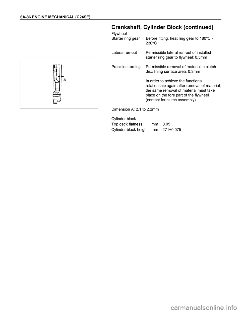
Crankshaft, Cylinder Block (continued)
Flywheel
Starter ring gear Before fitting, heat ring gear to 180�C -
230�C
Lateral run-out Permissible lateral run-out of installed
starter ring gear to flywheel: 0.5mm
Precision turning Permissible removal of material in clutch
disc lining surface area: 0.3mm
In order to achieve the functional
relationship again after removal of material,
the same removal of material must take
place on the fore part of the flywheel
(contact for clutch assembly)
Dimension A: 2.1 to 2.2mm
Cylinder block
Top deck flatness mm 0.05
Cylinder block height mm 271�0.075
Page 2507 of 4264
 6A-87
Recommended Torque Values
N�m (kgf�m)
Bearing cover to cylinder block ....................................................................................... 6")
ENGINE MECHANICAL (C24SE) 6A-87
Recommended Torque Values
N�m (kgf�m)
Bearing cover to cylinder block ....................................................................................... 60
1) 6.1 +40� to 50�
Bracket for alternator to cylinder block ............................................................................ 40 4.1
Bracket for engine damping block to transmission ......................................................... 60
2) 6.1
Bracket for engine damping block to engine block ......................................................... 60 6.1
Bracket for pump/compressor to engine block ............................................................... 35 3.6
Camshaft housing cover to housing ................................................................................ 8 0.8
Camshaft timing gear to camshaft .................................................................................. 50 5.1
Clamping bracket for alternator to intake manifold ......................................................... 25 2.5
Clamping bracket to alternator ........................................................................................ 25 2.5
Con-rod bearing cap to con-rod ...................................................................................... 35
1) 3.5 +45� to 60�
Crankshaft pulley bolts .................................................................................................... 20 2.0
Cylinder head to cylinder block ........................................................................................ 25
1)2) 2.5 +90� +90�
+90�
Engine damping block to engine bracket ........................................................................ 8.5 8.7
Engine damping block to side member ........................................................................... 52
1) 5.3
Exhaust manifold to cylinder head .................................................................................. 22 2.2
1) Use new bolts
2) Use new locking plates
Recommended Torque Values
N�m (kgf�m)
Flywheel to crankshaft ..................................................................................................... 65
1) 6.6 +30� to 45�
Front exhaust pipe to exhaust manifold .......................................................................... 25 2.5
Guide sleeve for pressure bearing to transmission ......................................................... 22 2.2
Intake manifold to cylinder head ...................................................................................... 22 2.2
Lower alternator bracket ................................................................................................. 25 2.5
Oil drain plug to oil pan .................................................................................................... 45 4.6
Oil intake pipe bracket to cylinder block .......................................................................... 6
2) 0.6
Oil intake pipe to oil pump ............................................................................................... 8 0.8
Oil pan to cylinder block .................................................................................................. 8
2)3) 0.8
Bearing bridge to cylinder block ...................................................................................... 8 2)3) 0.8
Oil pressure switch to oil pump ....................................................................................... 30 3.2
Pump for power steering (ribbed V-belt) to engine block ................................................ 30 3.2
Spark plugs in cylinder head ........................................................................................... 20 2.3
Starter support to cylinder block ...................................................................................... 25 2.5
Starter to cylinder block - engine side ............................................................................. 45 4.6
Starter to cylinder block - transmission side .................................................................... 75 7.6
Thermostat housing to cylinder head .............................................................................. 15 1.5
Toothed belt drive gear to crankshaft .............................................................................. 130
1) 13.3
Toothed belt front cover .................................................................................................. 4 0.4
Toothed belt rear cover ................................................................................................... 6 0.6
Toothed belt tension roller to oil pump ............................................................................ 20 2.3
(M10) ............................................................................ 45 4.6
Transmission to engine block ......................................................................................... 76 7.7
(M12) ............................................................................ 60 6.1
Water pump to cylinder block .......................................................................................... 17 1.7
1) Use new bolts
2) Use Locking Compound
3) Maximum installation time - 10 minutes
Page 2508 of 4264
6A-88 ENGINE MECHANICAL (C24SE)
SPECIAL SERVICE TOOLS
ITEM NO. ILLUSTRATION PART NO. PART NAME
5-8840-2634-0
Aligner
5-8840-2593-0
Cutter set
5-8840-2594-0
Spring Compressor
5-8840-0451-0
Installer
5-8840-0452-0
Remover / Installer
5-8840-2596-0
Distance Gauge
5-8840-0455-0
Assembly Sleeves
5-8840-2597-0
Installer
5-8840-0457-0
Remover / Installer
5-8840-0468-0
Remover / Installer
Page 2509 of 4264
ENGINE MECHANICAL (C24SE) 6A-89
ITEM NO. ILLUSTRATION PART NO. PART NAME
5-8840-0459-0
Installer
5-8840-0460-0
Installer
5-8840-0446-0
Flywheel Holder
5-8840-2598-0
Holding Wrench
5-8840-2599-0
Reamer Set
5-8840-2600-0
Socket Wrench
5-8840-2601-0
Installer

Crankshaft, Cylinder Block (continued)
Piston Rings
2.4L
Square ring Height mm 1.2
Tapered ring Height mm 1.5
Oil scraper Height mm 2.5
Ring")

Piston Pins
Dimensions
Length mm
Diameter mm
61.5
21
Type Shank-fit in con-rod
Clearance
In piston mm
In con-rod mm 2.4L
0.010 to 0.015
0
Installat")

SPECIAL SERVICE TOOLS
ITEM NO. ILLUSTRATION PART NO. PART NAME
5-8840-2634-0
Aligner
5-8840-2593-0
Cutter set
5-8840-2594-0")
 6A-89
ITEM NO. ILLUSTRATION PART NO. PART NAME
5-8840-0459-0
Installer
5-8840-0460-0
Installer
5-8840-0446-0
Flywheel Holder")