Page 3341 of 4264
IMMOBILIZER SYSTEM 11A-55
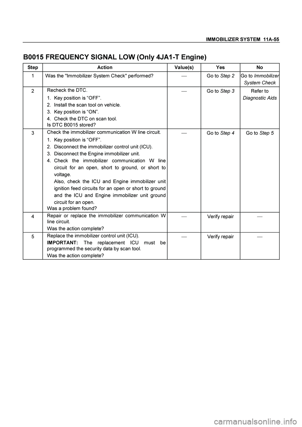
B0015 FREQUENCY SIGNAL LOW (Only 4JA1-T Engine)
Step Action Value(s) Yes No
1 Was the "Immobilizer System Check" performed? �
Go to Step 2
Go to Immobilizer
System Check
2 Recheck the DTC.
1. Key position is “OFF”.
2. Install the scan tool on vehicle.
3. Key position is “ON”.
4. Check the DTC on scan tool.
Is DTC B0015 stored? �
Go to Step 3
Refer to
Diagnostic Aids
3 Check the immobilizer communication W line circuit.
1. Key position is “OFF”.
2. Disconnect the immobilizer control unit (ICU).
3. Disconnect the Engine immobilizer unit.
4. Check the immobilizer communication W line
circuit for an open, short to ground, or short to
voltage.
Also, check the ICU and Engine immobilizer unit
ignition feed circuits for an open or short to ground
and the ICU and Engine immobilizer unit ground
circuit for an open.
Was a problem found? �
Go to Step 4
Go to Step 5
4 Repair or replace the immobilizer communication W
line circuit.
Was the action complete? �
Verify repair �
5 Replace the immobilizer control unit (ICU).
IMPORTANT:
The replacement ICU must be
programmed the security data by scan tool.
Was the action complete? �
Verify repair �
Page 3342 of 4264
11A-56 IMMOBILIZER SYSTEM
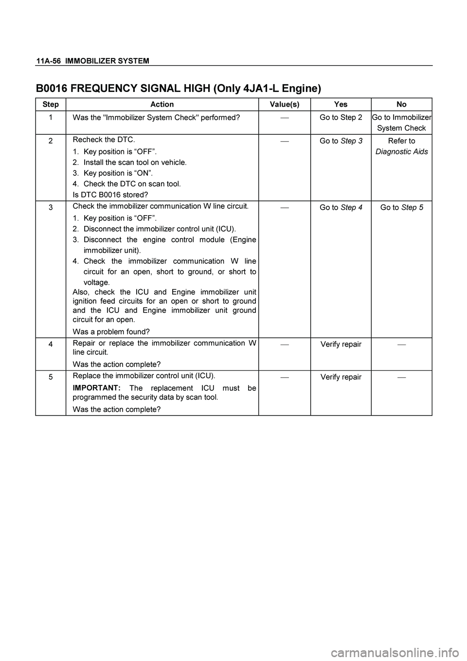
B0016 FREQUENCY SIGNAL HIGH (Only 4JA1-L Engine)
Step Action Value(s) Yes No
1
Was the "Immobilizer System Check" performed? �
Go to Step 2
Go to Immobilizer
System Check
2 Recheck the DTC.
1. Key position is “OFF”.
2. Install the scan tool on vehicle.
3. Key position is “ON”.
4. Check the DTC on scan tool.
Is DTC B0016 stored? �
Go to Step 3
Refer to
Diagnostic Aids
3 Check the immobilizer communication W line circuit.
1. Key position is “OFF”.
2. Disconnect the immobilizer control unit (ICU).
3. Disconnect the engine control module (Engine
immobilizer unit).
4. Check the immobilizer communication W line
circuit for an open, short to ground, or short to
voltage.
Also, check the ICU and Engine immobilizer unit
ignition feed circuits for an open or short to ground
and the ICU and Engine immobilizer unit ground
circuit for an open.
Was a problem found? �
Go to Step 4
Go to Step 5
4 Repair or replace the immobilizer communication W
line circuit.
Was the action complete? �
Verify repair
�
5 Replace the immobilizer control unit (ICU).
IMPORTANT:
The replacement ICU must be
programmed the security data by scan tool.
Was the action complete? �
Verify repair �
Page 3343 of 4264
IMMOBILIZER SYSTEM 11A-57
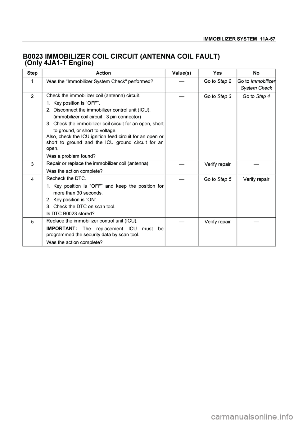
B0023 IMMOBILIZER COIL CIRCUIT (ANTENNA COIL FAULT)
(Only 4JA1-T Engine)
Step Action Value(s) Yes No
1
Was the "Immobilizer System Check" performed? �
Go to Step 2
Go to Immobilizer
System Check
2 Check the immobilizer coil (antenna) circuit.
1. Key position is “OFF”.
2. Disconnect the immobilizer control unit (ICU).
(immobilizer coil circuit : 3 pin connector)
3. Check the immobilizer coil circuit for an open, short
to ground, or short to voltage.
Also, check the ICU ignition feed circuit for an open or
short to ground and the ICU ground circuit for an
open.
Was a problem found? �
Go to Step 3
Go to Step 4
3 Repair or replace the immobilizer coil (antenna).
Was the action complete? �
Verify repair �
4 Recheck the DTC.
1. Key position is “OFF” and keep the position for
more than 30 seconds.
2. Key position is “ON”.
3. Check the DTC on scan tool.
Is DTC B0023 stored? �
Go to Step 5
Verify repair
5 Replace the immobilizer control unit (ICU).
IMPORTANT:
The replacement ICU must be
programmed the security data by scan tool.
Was the action complete? �
Verify repair �
Page 3344 of 4264
11A-58 IMMOBILIZER SYSTEM
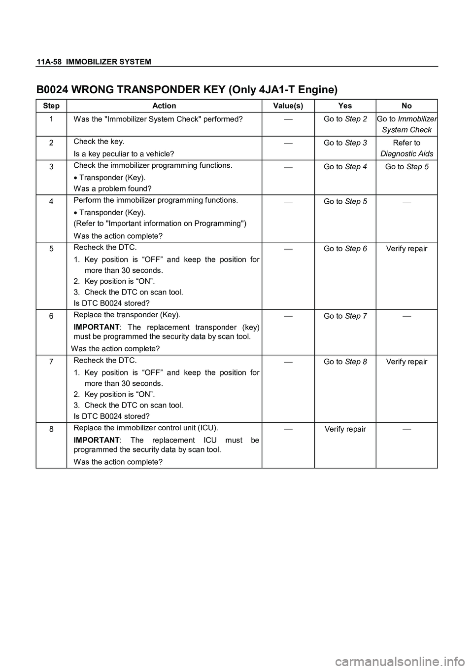
B0024 WRONG TRANSPONDER KEY (Only 4JA1-T Engine)
Step Action Value(s) Yes No
1
W as the "Immobilizer System Check" performed? �
Go to Step 2
Go to Immobilizer
System Check
2 Check the key.
Is a key peculiar to a vehicle? �
Go to Step 3
Refer to
Diagnostic Aids
3 Check the immobilizer programming functions.
�
Transponder (Key).
W as a problem found? �
Go to Step 4
Go to Step 5
4 Perform the immobilizer programming functions.
� Transponder (Key).
(Refer to "Important information on Programming")
W as the action complete? �
Go to Step 5 �
5 Recheck the DTC.
1. Key position is “OFF” and keep the position for
more than 30 seconds.
2. Key position is “ON”.
3. Check the DTC on scan tool.
Is DTC B0024 stored? �
Go to Step 6
Verify repair
6 Replace the transponder (Key).
IMPORTANT
: The replacement transponder (key)
must be programmed the security data by scan tool.
Was the action complete? �
Go to Step 7 �
7 Recheck the DTC.
1. Key position is “OFF” and keep the position for
more than 30 seconds.
2. Key position is “ON”.
3. Check the DTC on scan tool.
Is DTC B0024 stored? �
Go to Step 8
Verify repair
8 Replace the immobilizer control unit (ICU).
IMPORTANT
: The replacement ICU must be
programmed the security data by scan tool.
W as the action complete? �
Verify repair
�
Page 3353 of 4264
ANTITHEFT SYSTEM 11B – 7
DIAGRAMS AND SCHEMATICS
SYSTEM WIRING DIAGRAMS
M
M
M
M
M
M
M
M
- +
ANTITHEFT CONTROL UNIT BATTERY
(12V)
80A10A
ACC Ignition switch20A
10A
10A
antitheft horn
power supply
power supply
door lock motors
hazard relay(RH)
flashers(RH)
hazard relay(LH)
flashers(LH)
status LED
immobilizer controller
daiagnostc conector
groundlock lock
locklock lock alarm trigger
super lock
unlock unlock
(unlock)
(unlock)
unlock
driver door rear door(LH) rear door(RH)rear door(LH) rear door(RH)
assist door driver door assist doordriver door
assist door
driver door assist door
engine hood contact switch
door contact switch
auto door lock switch auto door lock
door lock cylinder
disarmwith super
lock without
super lock
Page 3354 of 4264
11B – 8 ANTITHEFT SYSTEM
ANTI-THEFT INDICATER SIDE TURN SIGNAL , HAZARD
WARNING LIGHT ; RH
ANTI-THEFT HORN FRT TURN SIGNAL , HAZARD
WARNING LIGHT ; RH
ENGINE HOOD SWANTI-THEFT
CONTROLLERRR DOOR SW ; RH
FRT DOOR LOCKACTUATOR ; RHFRT DOOR KEY SW ; RHFRT DOOR SW ; RH
RR DOOR LOCK ACTUATOR ; RHFRT DOOR SW ; LH
RR DOOR LOCK ACTUATOR ; LH RR DOOR SW ; LH
FRT DOOR LOCKACTUATOR ; LHFRT DOOR KEY SW ; LH
SIDE TURN SIGNAL , HAZARD
WARNING LIGHT ; LH FRT TURN SIGNAL , HAZARD
WARNING LIGHT ; LHRELAY ; HAZARD
RR TURN SIGNAL , HAZARD
WARNING LIGHT ; LH
RAW4C0XF000201
COMPONENT WIRING LOCATORS (LHD)
Page 3357 of 4264
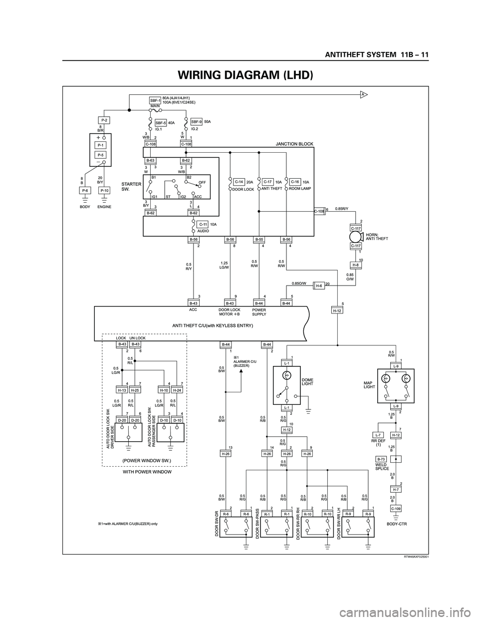
ANTITHEFT SYSTEM 11B – 11
RTW48AXF025001
A
DOOR SW-DR
B-73
DOOR SW-PASSDOOR SW-RR RHDOOR SW-RR LH
L-7
0.5
B/W0.5
B/W0.5
B/W
0.5
R/G0.5
R/G0.5
R/G 0.5
R/G0.5
R/G
1
ALARMER C/U
(BUZZER)
1=with ALARMER C/U(BUZZER) only0.5
R/G0.5
R/G0.5
R/W
1.25
B
1.25
B
2.0
B
2.0
B
DOME
LIGHTHORN;
ANTI THEFT
L-91
H-72 L-9
2
RR DEF
(1)
WELD
SPLICE MAP
LIGHT
C-109
BODY-CTR
R-62
R-61
R-11
R-101
R-91 2
H-26L-11
L-1
2
H-1210
H-127R-1R-10R-9
0.5
R/B0.5
R/B
0.5
R/B0.5
R/B
2 2 2
9
H-2614
H-2613
H-26
C-11 10A
AUDIO
2 B-56 3
B-624 2
B-62 B-62
3 B-63
P-6P-5
8
BIG.1IG.2 MAIN
20
B/Y8
B/R
3
W/B
3
W3
W/B
3
B/Y
0.5
R/Y0.5
R/W0.5
R/W0.85R/Y
0.85
O/W
0.85O/W 1.25
LG/W 5
W
P-11
C-108 2
C-108
B1 B2
IG1 IG2 ACCOFF
ST
P-10P-2SBF-180A (4JA1/4JH1)
100A (6VE1/C24SE)
DOOR LOCKC-14
20A
ANTI THEFTC-17
10A
ROOM LAMPC-16
10A SBF-540A50A
SBF-9
BODY ENGINE
JANCTION BLOCK
B-56
8
B-43
2B-43
6
H-134
H-257
D-207
D-206H-104
H-247
D-103
D-104B-44
1B-44
2 4
B-445
B-442
C-117
5
H-12 9
B-43 3
B-43B-55
4B-56C-108
4
H-810 C-117
1 6
H-620
AUTO DOOR LOCK SW.
DRIVER SIDE
AUTO DOOR LOCK SW.
PASSENGER SIDE
0.5
LG/R
0.5
LG/R0.5
LG/R 0.5
R/L
0.5
R/L0.5
R/L
(POWER WINDOW SW.)
LOCK UN LOCK
WITH POWER WINDOW
DOOR LOCK
MOTORB ACC
ANTI THEFT C/U(with KEYLESS ENTRY) STARTER
SW.
3
L
POWER
SUPPLY
RTW48AXF025001
WIRING DIAGRAM (LHD)
Page 3358 of 4264
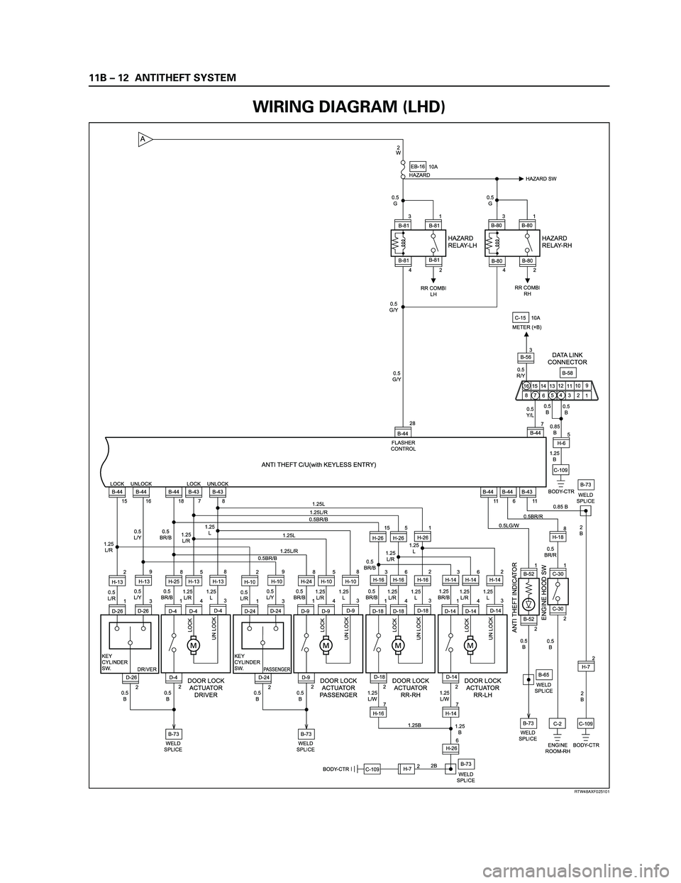
11B – 12 ANTITHEFT SYSTEM
7
B-440.5
B 0.5
Y/L 0.5
R/Y
0.85
B0.5
B 0.5
G/Y0.5
G0.5
G
0.5
G/Y2
W
10A
HAZARDEB-16
1.25
B
C-109B-58 C-15
BODY-CTRH-65 28
B-44
B-43
11 B-43 UNLOCK
8 B-43 LOCK
7 B-44
18 B-44 UNLOCK
16 B-44 LOCK
151
B-80 3
B-80
4 B-80
2 B-80
HAZARD
RELAY-LHHAZARD
RELAY-RH
HAZARD SW
1
B-81 3
B-81
4 B-81
2 B-81
DATA LINK
CONNECTOR
RR COMBI
LHRR COMBI
RH
B-73 D-261
D-26 D-4D-263 H-132
H-139
D-44
D-41
D-43 H-135
H-258
H-138
0.5
L/R1.25
L/R 1.25
L/R
1.25
L 0.5
L/Y0.5
L/Y
0.5
BR/B
22
LOCK
UN LOCK
KEY
CYLINDER
SW.
DRIVER
PASSENGER
DOOR LOCK
ACTUATOR
DRIVER
0.5
B0.5
BFLASHER
CONTROL
ANTI THEFT C/U(with KEYLESS ENTRY)
1 3 4
5
7 89
10
11 12
13 14 15
162
6 B-56310A
METER (+B)
2
B
2
B
C-109
BODY-CTR B-44
6
C-2
ENGINE
ROOM-RHH-72 0.85 B
0.5BR/R
0.5
BR/R
0.5
B 0.5
B 0.5LG/WWELD
SPLICEB-73
WELD
SPLICEB-73WELD
SPLICEB-65
WELD
SPLICEB-73 D-241
D-24 D-9D-243 H-102
H-109
D-94
D-91
D-93 H-105
H-248
H-108
0.5
L/R1.25
L/R1.25
L 1.25L
1.25L/R
0.5BR/B
1.25L
1.25L/R
0.5BR/B
0.5
L/Y0.5
BR/B
22
LOCK
UN LOCK
KEY
CYLINDER
SW.
DOOR LOCK
ACTUATOR
PASSENGER
0.5
B0.5
B
WELD
SPLICEB-73
WELD
SPLICE D-18
D-184
D-181
D-183 H-265
H-2615
H-261
H-166
H-163
H-162
1.25
L/R1.25
L 0.5
BR/B1.25
L/R1.25
L
0.5
BR/B 1.25
L/R1.25
L 0.5
BR/B
2
LOCK
UN LOCK
DOOR LOCK
ACTUATOR
RR-RH
1.25
L/WD-14
D-144
D-141
D-143 H-146
H-143
H-142
1.25
L/R1.25
L 1.25
BR/B
2
2H-26
LOCK
UN LOCK
DOOR LOCK
ACTUATOR
RR-LH
ANTI THEFT INDICATOR
ENGINE HOOD SW
1.25
L/W
1.25
B
2B 1.25B
A
C-301 H-188
2 C-30
B-44
11
BODY-CTR
B-521
2 B-52
H-7
H-147
6 H-167
C-109
RTW48AXF025101
WIRING DIAGRAM (LHD)