Page 3362 of 4264
11B – 16 ANTITHEFT SYSTEM
A
DOOR SW-DR
B-73
DOOR SW-PASSDOOR SW-RR RHDOOR SW-RR LH
L-7
0.5
B/W0.5
B/W0.5
B/W
0.5
R/G0.5
R/G0.5
R/G 0.5
R/G0.5
R/G
1
ALARMER C/U
(BUZZER)
1=with ALARMER C/U(BUZZER) only0.5
R/G0.5
R/G0.5
R/W
1.25
B
1.25
B
2.0
B
2.0
B
DOME
LIGHTHORN;
ANTI THEFT
L-91
H-185 L-9
2
RR DEF
(1)
WELD
SPLICE MAP
LIGHT
C-2
ENGINE �
ROOM RH
R-62
R-61
R-11
R-101
R-91 2
H-26L-11
L-1
2
H-1210
H-127R-1R-10R-9
0.5
R/B0.5
R/B
0.5
R/B0.5
R/B
2 2 2
9
H-2614
H-2613
H-26
C-11 10A
AUDIO
2 B-56 3
B-624 2
B-62 B-62
3 B-63
P-6P-5
8
BIG.1IG.2 MAIN
20
B/Y8
B/R
3
W/B
3
W3
W/B
3
B/Y
0.5
R/Y0.5
R/W0.5
R/W0.85R/Y
1.25
LG/W 5
W
P-11
C-108 2
C-108
B1 B2
IG1 IG2 ACCOFF
ST
P-10P-2SBF-180A (4JA1/4JH1)
100A (6VE1/C24SE)
DOOR LOCKC-14
20A
ANTI THEFTC-17
10A
ROOM LAMPC-16
10A SBF-540A50A
SBF-9
BODY ENGINE
JANCTION BLOCK
B-56
8
B-43
2B-43
6
H-104
H-247
D-207
D-206H-134
H-257
D-103
D-104B-44
1B-44
2 4
B-445
B-442
C-117
5
H-12 9
B-43 3
B-43B-55
4B-56C-108
4
H-181 C-117
1 6
AUTO DOOR LOCK SW.
DRIVER SIDE
AUTO DOOR LOCK SW.
PASSENGER SIDE
0.5
LG/R
0.5
LG/R0.5
LG/R 0.5
R/L
0.5
R/L0.5
R/L
(POWER WINDOW SW.)
LOCK UN LOCK
WITH POWER WINDOW
DOOR LOCK
MOTORB ACC
ANTI THEFT C/U(with KEYLESS ENTRY) STARTER
SW.
3
L
POWER
SUPPLY
RTW48AXF023901
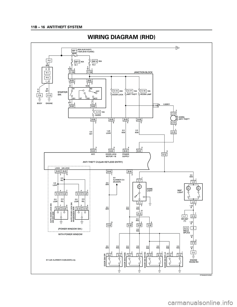
WIRING DIAGRAM (RHD)
Page 3363 of 4264
ANTITHEFT SYSTEM 11B – 17
ALARM
TRIGGER7
B-440.5
B 0.5
Y/L 0.5
R/Y
0.85
B0.5
B 0.5
G/Y0.5
G0.5
G
0.5
G/Y2
W
10A
HAZARDEB-16
1.25
B
C-2B-58 C-15
ENGINE
ROOM-RHH-183 H-712
28
B-44
B-43
11 B-43 UNLOCK
8 B-43 LOCK
7 B-44
18 B-44 UNLOCK
16 B-44 LOCK
151
X-9 3
X-9
4 X-9
2 X-9
HAZARD
RELAY-LHHAZARD
RELAY-RH
HAZARD SW
1
X-10 3
X-10
4 X-10
2 X-10
DATA LINK
CONNECTOR
RR COMBI
LHRR COMBI
RH
B-73 D-241
D-24 D-4D-243 H-102
H-109
D-44
D-41
D-43 H-105
H-248
H-108
0.5
L/R1.25
L/R 1.25
L/R
1.25
L 0.5
L/Y0.5
L/Y
0.5
BR/B
22
LOCK
UN LOCK
KEY
CYLINDER
SW.
DOOR LOCK
ACTUATOR
DRIVER
0.5
B0.5
BFLASHER
CONTROL
ANTI THEFT C/U(with KEYLESS ENTRY)
1 3 4
5
7 89
10
11 12
13 14 15
162
6 B-56310A
METER (+B)
2
B
2
B
C-2
ENGINE
ROOM-RH B-44
6
C-2
ENGINE
ROOM-RHH-185 0.85 B
0.5BR/R
0.5
BR/R
0.5
B 0.5
B
1.25
B 0.5LG/WWELD
SPLICEB-73
WELD
SPLICEB-73 WELD
SPLICEB-73 D-261
D-26 D-9D-263 H-132
H-139
D-94
D-91
D-93 H-135
H-258
H-138
0.5
L/R1.25
L/R1.25
L 1.25L
1.25L/R
0.5BR/B
1.25L
1.25L/R
0.5BR/B
0.5
L/Y0.5
BR/B
22
LOCK
UN LOCK
KEY
CYLINDER
SW.
DOOR LOCK
ACTUATOR
PASSENGER
0.5
B0.5
B
WELD
SPLICED-18
D-184
D-181
D-183 H-265
H-2615
H-261
H-166
H-163
H-162
1.25
L/R1.25
L 0.5
BR/B1.25
L/R1.25
L
0.5
BR/B 1.25
L/R1.25
L 0.5
BR/B
2
LOCK
UN LOCK
DOOR LOCK
ACTUATOR
RR-RH
1.25
L/WD-14
D-144
D-141
D-143 H-146
H-143
H-142
1.25
L/R1.25
L 1.25
BR/B
2
5H-26
LOCK
UN LOCK
DOOR LOCK
ACTUATOR
RR-LH
ANTI THEFT INDICATOR
ENGINE HOOD SW
1.25
L/W
1.25
B
2B 1.25B
A
C-301 H-188
2 C-30
B-44
11
C-2
ENGINE
ROOM-RH
ENGINE
ROOM-RH
B-521
2 B-52
H-18
H-183
H-147
6 H-167
C-2
RTW48AXF024001
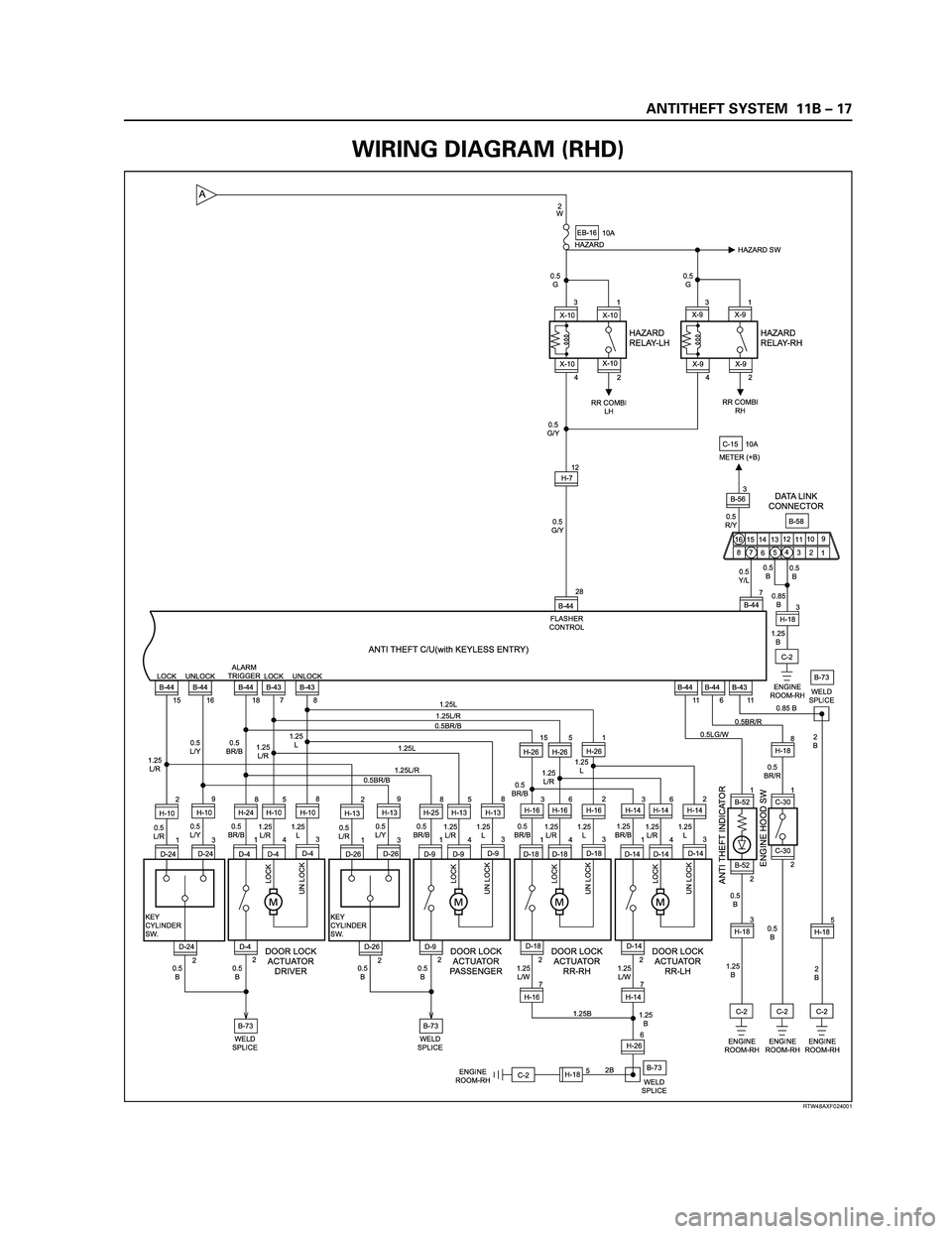
WIRING DIAGRAM (RHD)
Page 3364 of 4264
11B – 18 ANTITHEFT SYSTEM
A
DOOR SW-DR
B-73
DOOR SW-PASSDOOR SW-RR RHDOOR SW-RR LH
L-7
0.5
B/W0.5
B/W0.5
B/W
0.5
R/G0.5
R/G0.5
R/G 0.5
R/G0.5
R/G
1
ALARMER C/U
(BUZZER)
1=with ALARMER C/U(BUZZER) only0.5
R/G0.5
R/G0.5
R/W
1.25
B
1.25
B
2.0
B
2.0
B
DOME
LIGHTHORN;
ANTI THEFT
L-91
H-185 L-9
2
RR DEF
(1)
WELD
SPLICE MAP
LIGHT
C-2
ENGINE �
ROOM RH
R-62
R-61
R-11
R-101
R-91 2
H-26L-11
L-1
2
H-1210
H-127R-1R-10R-9
0.5
R/B0.5
R/B
0.5
R/B0.5
R/B
2 2 2
9
H-2614
H-2613
H-26
C-11 10A
AUDIO
2 B-56 3
B-624 2
B-62 B-62
3 B-63
P-6P-5
8
BIG.1IG.2 MAIN
20
B/Y8
B/R
3
W/B
3
W3
W/B
3
B/Y
0.5
R/Y0.5
R/W0.5
R/W0.85R/Y
1.25
LG/W 5
W
P-11
C-108 2
C-108
B1 B2
IG1 IG2 ACCOFF
ST
P-10P-2SBF-180A (4JA1/4JH1)
100A (6VE1/C24SE)
DOOR LOCKC-14
20A
ANTI THEFTC-17
10A
ROOM LAMPC-16
10A SBF-540A50A
SBF-9
BODY ENGINE
JANCTION BLOCK
B-56
8
B-43
2B-43
6
H-104
H-247
D-207
BD-206H-134
H-257
D-103
D-104B-44
1B-44
2 4
B-445
B-442
C-117
5
H-12 9
B-43 3
B-43B-55
4B-56C-108
4
H-181 C-117
1 6
AUTO DOOR LOCK SW.
DRIVER SIDE
AUTO DOOR LOCK SW.
PASSENGER SIDE
0.5
LG/R
0.5
LG/R0.5
LG/R 0.5
R/L
0.5
R/L0.5
R/L
(POWER WINDOW SW.)
LOCK UN LOCK
WITH POWER WINDOW
DOOR LOCK
MOTORB ACC
ANTI THEFT C/U with SUPER LOCK STARTER
SW.
3
L
POWER
SUPPLY
RTW48AXF025401
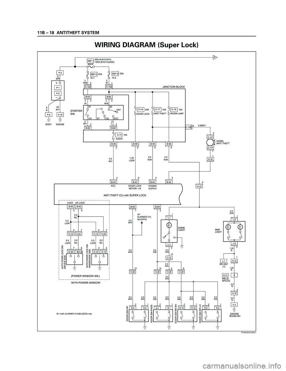
WIRING DIAGRAM (Super Lock)
Page 3366 of 4264
11B – 20 ANTITHEFT SYSTEM
RTW48AXF024901
ANTI THEFT INDICATOR
ENGINE HOOD SW
7
B-440.5
B 0.5
Y/L
0.3
V0.5
R/Y
0.85
B0.5
B
1.25
B
C-2B-58 C-15
ENGINE
ROOM-RHH-183
B-43
11
DATA LINK
CONNECTOR
IMMOBILIZER C/U
ANTI THEFT C/U with SUPER LOCK
1 3 4
5
7 89
10
11 12
13 14 15
162
6 B-563
9
B-44 B-68
610A
METER (+B)
2
B
2
B
C-2
ENGINE
ROOM-RH B-44
6
C-2
ENGINE
ROOM-RHH-185 0.85 B
0.5BR/R
0.5
BR/R
0.5
B 0.5
B
1.25
B 0.5LG/WWELD
SPLICEB-73
WELD
SPLICEB-73 D-18
D-271
D-274
D-272 H-265
H-2615
H-261
H-166
H-163
H-162
1.25
L/R1.25
L 0.5
BR/B1.25
L/R1.25
L
0.5
BR/B
7
LOCK
UN LOCKLOCK UN LOCKLOCK UN LOCK
DOOR LOCK
ACTUATOR
RR-RH
1.25
L/WD-14
D-281
D-284
D-282 H-146
H-143
H-142
1.25
L/R1.25
L
D-283
D-286H-147
D-273 H-269
D-276H-167
1.25
BR/B
2
5H-26
LOCK
UN LOCK
DOOR LOCK
ACTUATOR
RR-LH
1.25
L/W
1.25
B
2B 1.25B
E
B
C
D
C-301 H-188
2 C-30
B-44
11
C-2
ENGINE
ROOM-RH
ENGINE
ROOM-RH
B-521
2 B-52
H-18
H-183
H-147
6 H-167
C-2
RTW48AXF024901
WIRING DIAGRAM (Super Lock)
Page 3368 of 4264
11B – 22 ANTITHEFT SYSTEM
Pin-Assignment
No. Pin Assignment 28 PIN
1 Contact switch driver door
2 Contact switch doors
3—
4 Power supply antitheft
5 horn
6 Contact switch engine compartment
7 Diagnosis
8—
9—
10 —
11 Status LED
12 —
13 —
14 —
15 Lock driver side door lock cylinder
16 Unlock driver side door lock cylinder
17 —
18 Micro Switch, lock / unlock door lock motor
19 —
20 —
21 —
22 —
23 —
24 —
25 —
26 —
27 —
28 Flasher control
No. Pin Assignment 12 PIN
1—
2—
3 Key in
4—
5—
6 Micro Switch, unlock, auto door lock
7 Lock, locking motors
8 Unlock, locking motors
9 Power supply locking motors
10 —
11 Ground
12 —
Page 3380 of 4264
11B – 34 ANTITHEFT SYSTEM
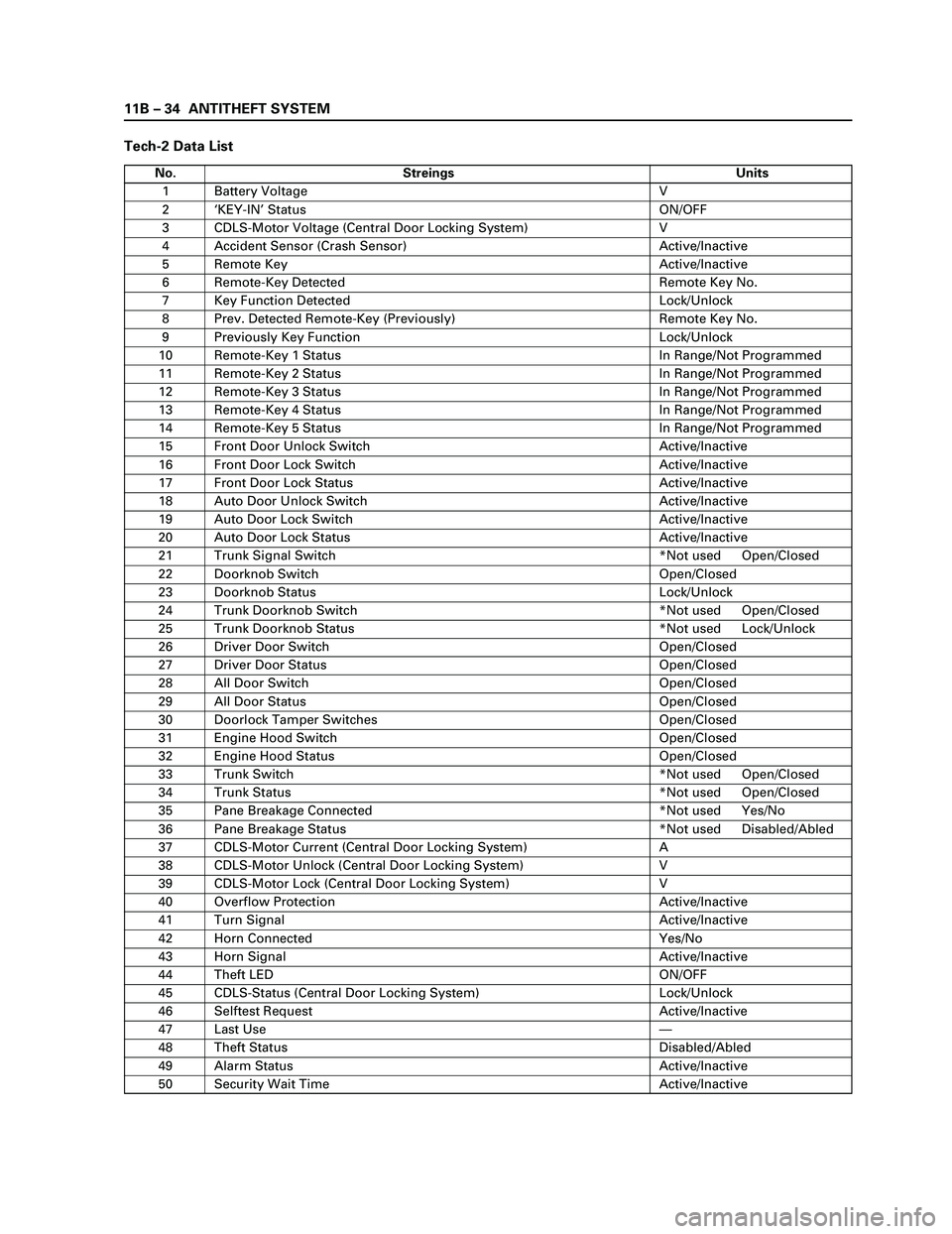
Tech-2 Data List
No. Streings Units
1 Battery Voltage V
2‘KEY-IN’ Status ON/OFF
3 CDLS-Motor Voltage (Central Door Locking System) V
4 Accident Sensor (Crash Sensor) Active/Inactive
5 Remote Key Active/Inactive
6 Remote-Key Detected Remote Key No.
7 Key Function Detected Lock/Unlock
8 Prev. Detected Remote-Key (Previously) Remote Key No.
9 Previously Key Function Lock/Unlock
10 Remote-Key 1 Status In Range/Not Programmed
11 Remote-Key 2 Status In Range/Not Programmed
12 Remote-Key 3 Status In Range/Not Programmed
13 Remote-Key 4 Status In Range/Not Programmed
14 Remote-Key 5 Status In Range/Not Programmed
15 Front Door Unlock Switch Active/Inactive
16 Front Door Lock Switch Active/Inactive
17 Front Door Lock Status Active/Inactive
18 Auto Door Unlock Switch Active/Inactive
19 Auto Door Lock Switch Active/Inactive
20 Auto Door Lock Status Active/Inactive
21 Trunk Signal Switch *Not used Open/Closed
22 Doorknob Switch Open/Closed
23 Doorknob Status Lock/Unlock
24 Trunk Doorknob Switch *Not used Open/Closed
25 Trunk Doorknob Status *Not used Lock/Unlock
26 Driver Door Switch Open/Closed
27 Driver Door Status Open/Closed
28 All Door Switch Open/Closed
29 All Door Status Open/Closed
30 Doorlock Tamper Switches Open/Closed
31 Engine Hood Switch Open/Closed
32 Engine Hood Status Open/Closed
33 Trunk Switch *Not used Open/Closed
34 Trunk Status *Not used Open/Closed
35 Pane Breakage Connected *Not used Yes/No
36 Pane Breakage Status *Not used Disabled/Abled
37 CDLS-Motor Current (Central Door Locking System) A
38 CDLS-Motor Unlock (Central Door Locking System) V
39 CDLS-Motor Lock (Central Door Locking System) V
40 Overflow Protection Active/Inactive
41 Turn Signal Active/Inactive
42 Horn Connected Yes/No
43 Horn Signal Active/Inactive
44 Theft LED ON/OFF
45 CDLS-Status (Central Door Locking System) Lock/Unlock
46 Selftest Request Active/Inactive
47 Last Use—
48 Theft Status Disabled/Abled
49 Alarm Status Active/Inactive
50 Security Wait Time Active/Inactive
Page 3383 of 4264
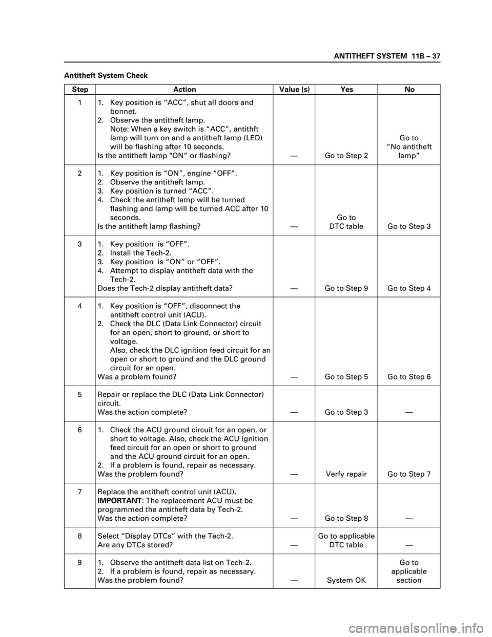
ANTITHEFT SYSTEM 11B – 37
Antitheft System Check
Step Action Value (s) Yes No
1
2
3
4
5
6
7
8
91. Key position is “ACC”, shut all doors and
bonnet.
2. Observe the antitheft lamp.
Note: When a key switch is “ACC”, antithft
lamp will turn on and a antitheft lamp (LED)
will be flashing after 10 seconds.
Is the antitheft lamp "ON” or flashing?
1. Key position is “ON”, engine “OFF”.
2. Observe the antitheft lamp.
3. Key position is turned “ACC”.
4. Check the antitheft lamp will be turned
flashing and lamp will be turned ACC after 10
seconds.
Is the antitheft lamp flashing?
1. Key position is “OFF”.
2. Install the Tech-2.
3. Key position is “ON” or “OFF”.
4. Attempt to display antitheft data with the
Tech-2.
Does the Tech-2 display antitheft data?
1. Key position is “OFF”, disconnect the
antitheft control unit (ACU).
2. Check the DLC (Data Link Connector) circuit
for an open, short to ground, or short to
voltage.
Also, check the DLC ignition feed circuit for an
open or short to ground and the DLC ground
circuit for an open.
Was a problem found?
Repair or replace the DLC (Data Link Connector)
circuit.
Was the action complete?
1. Check the ACU ground circuit for an open, or
short to voltage. Also, check the ACU ignition
feed circuit for an open or short to ground
and the ACU ground circuit for an open.
2. If a problem is found, repair as necessary.
Was the problem found?
Replace the antitheft control unit (ACU).
IMPORTANT: The replacement ACU must be
programmed the antitheft data by Tech-2.
Was the action complete?
Select “Display DTCs” with the Tech-2.
Are any DTCs stored?
1. Observe the antitheft data list on Tech-2.
2. If a problem is found, repair as necessary.
Was the problem found?—
—
—
—
—
—
—
—
—Go to Step 2
Go to
DTC table
Go to Step 9
Go to Step 5
Go to Step 3
Verfy repair
Go to Step 8
Go to applicable
DTC table
System OKGo to
“No antitheft
lamp”
Go to Step 3
Go to Step 4
Go to Step 6
—
Go to Step 7
—
—
Go to
applicable
section
Page 3437 of 4264
POWER-ASSISTED STEERING SYSTEM 3B-7
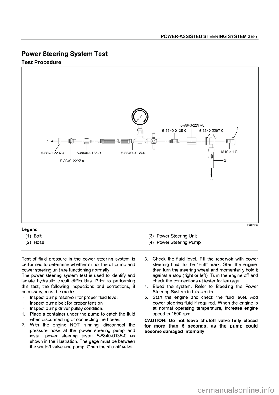
Power Steering System Test
Test Procedure
F02RX002
Legend
(1) Bolt
(2) Hose
(3) Power Steering Unit
(4) Power Steering Pump
Test of fluid pressure in the power steering system is
performed to determine whether or not the oil pump and
power steering unit are functioning normally.
The power steering system test is used to identify and
isolate hydraulic circuit difficulties. Prior to performing
this test, the following inspections and corrections, i
f
necessary, must be made.
��
Inspect pump reservoir for proper fluid level.
��
Inspect pump belt for proper tension.
��
Inspect pump driver pulley condition.
1. Place a container under the pump to catch the fluid
when disconnecting or connecting the hoses.
2.
With the engine NOT running, disconnect the
pressure hose at the power steering pump and
install power steering tester 5-8840-0135-0 as
shown in the illustration. The gage must be between
the shutoff valve and pump. Open the shutoff valve.
3. Check the fluid level. Fill the reservoir with powe
r
steering fluid, to the "Full" mark. Start the engine,
then turn the steering wheel and momentarily hold it
against a stop (right or left). Turn the engine off and
check the connections at tester for leakage.
4. Bleed the system. Refer to Bleeding the Powe
r
Steering System in this section.
5. Start the engine and check the fluid level. Add
power steering fluid if required. When the engine is
at normal operating temperature, increase engine
speed to 1500 rpm.
CAUTION: Do not leave shutoff valve fully closed
for more than 5 seconds, as the pump could
become damaged internally.