Page 3322 of 4264

11A-36 IMMOBILIZER SYSTEM
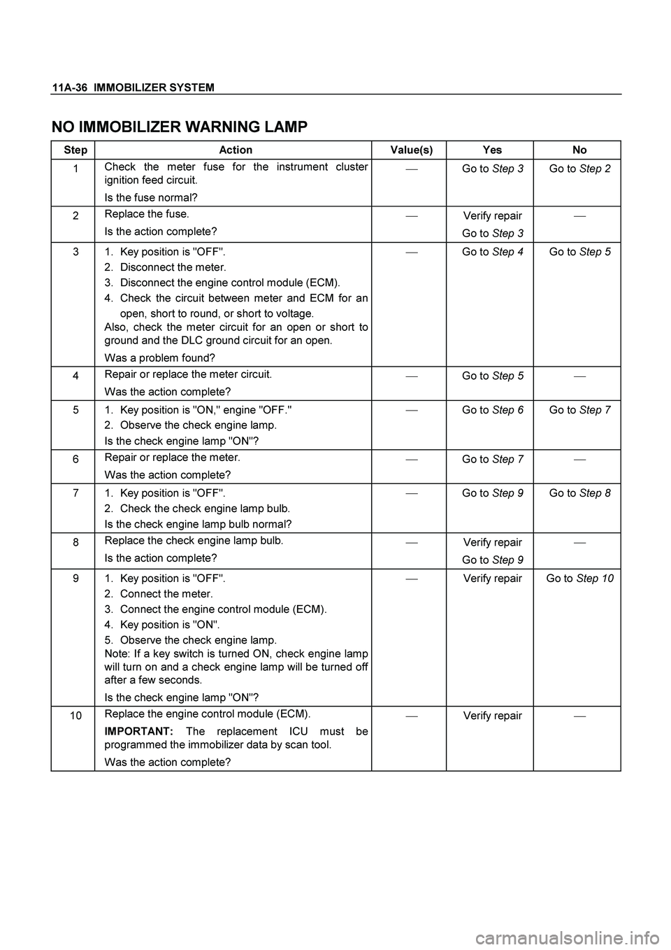
NO IMMOBILIZER WARNING LAMP
Step Action Value(s) Yes No
1 Check the meter fuse for the instrument cluster
ignition feed circuit.
Is the fuse normal? �
Go to Step 3
Go to Step 2
2 Replace the fuse.
Is the action complete? �
Verify repair
Go to Step 3 �
3 1. Key position is "OFF".
2. Disconnect the meter.
3. Disconnect the engine control module (ECM).
4. Check the circuit between meter and ECM for an
open, short to round, or short to voltage.
Also, check the meter circuit for an open or short to
ground and the DLC ground circuit for an open.
Was a problem found? �
Go to Step 4
Go to Step 5
4 Repair or replace the meter circuit.
Was the action complete? �
Go to Step 5
�
5 1. Key position is "ON," engine "OFF."
2. Observe the check engine lamp.
Is the check engine lamp "ON"? �
Go to Step 6
Go to Step 7
6 Repair or replace the meter.
Was the action complete? �
Go to Step 7 �
7 1. Key position is "OFF".
2. Check the check engine lamp bulb.
Is the check engine lamp bulb normal? �
Go to Step 9
Go to Step 8
8 Replace the check engine lamp bulb.
Is the action complete? �
Verify repair
Go to Step 9 �
9 1. Key position is "OFF".
2. Connect the meter.
3. Connect the engine control module (ECM).
4. Key position is "ON".
5. Observe the check engine lamp.
Note: If a key switch is turned ON, check engine lamp
will turn on and a check engine lamp will be turned off
after a few seconds.
Is the check engine lamp "ON"? �
Verify repair
Go to Step 10
10 Replace the engine control module (ECM).
IMPORTANT: The replacement ICU must be
programmed the immobilizer data by scan tool.
Was the action complete? �
Verify repair �
Page 3355 of 4264
ANTITHEFT SYSTEM 11B – 9
E
A
DE
CB D
D-24
D-26
D-14
D-4
D-20
L-7
H-14
R-1
P-1 D-9(EUROPE)
2nd Battery
D-18P-5
P-6
C-30 C-2
C-117
C-109
H-13
H-7
H-25
H-6
P-2R-9 L-1 L-9
JUNCTION BLOCK
B-8,B-7,B-40 RELAY
C-1
C20 FUSE
X-1
X-15 RELAY
EB-1EB16 FUSE X-16, X-17 DIODE
SBF-1SBF-9 SLOW BLOW FUSE
R-10
H-16
H-8
H-26 H-10
H-24R-6
RTW48AXF025201
WIRING DIAGRAM (LHD)
Page 3360 of 4264
11B – 14 ANTITHEFT SYSTEM
B
A
C
R-10
H-16
L-7 (EUROPE)
2nd Battery
D-25D-28
D-26 D-10
H-14
R-1
P-1 D-20
D-24
D-23
P-10P-5
P-6
C-30 C-2
C-117
H-25
H-13
P-2R-9 L-1 L-9 JUNCTION BLOCK
B-8,B-7,B-40 RELAY
C-1
C20 FUSE
X-1
X-15 RELAY
EB-1EB16 FUSE X-16, X-17 DIODE
SBF-1SBF-9 SLOW BLOW FUSE
H-18D-27
H-26 H-10
H-24R-6
RTW48AXF025501
WIRING DIAGRAM (Super Lock)
Page 3384 of 4264

11B – 38 ANTITHEFT SYSTEM
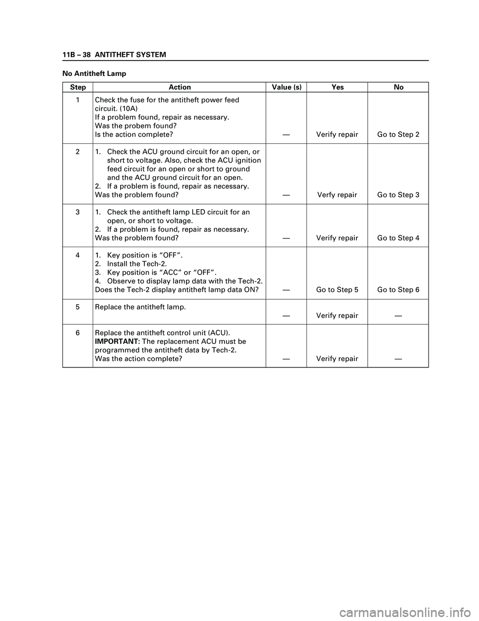
No Antitheft Lamp
Step Action Value (s) Yes No
1
2
3
4
5
6Check the fuse for the antitheft power feed
circuit. (10A)
If a problem found, repair as necessary.
Was the probem found?
Is the action complete?
1. Check the ACU ground circuit for an open, or
short to voltage. Also, check the ACU ignition
feed circuit for an open or short to ground
and the ACU ground circuit for an open.
2. If a problem is found, repair as necessary.
Was the problem found?
1. Check the antitheft lamp LED circuit for an
open, or short to voltage.
2. If a problem is found, repair as necessary.
Was the problem found?
1. Key position is “OFF”.
2. Install the Tech-2.
3. Key position is “ACC” or “OFF”.
4. Observe to display lamp data with the Tech-2.
Does the Tech-2 display antitheft lamp data ON?
Replace the antitheft lamp.
Replace the antitheft control unit (ACU).
IMPORTANT:The replacement ACU must be
programmed the antitheft data by Tech-2.
Was the action complete?—
—
—
—
—
—Verify repair
Verfy repair
Verify repair
Go to Step 5
Verify repair
Verify repairGo to Step 2
Go to Step 3
Go to Step 4
Go to Step 6
—
—
Page 3659 of 4264
TRANSFER CONTROL SYSTEM 7D1-33
No. Connector face No. Connector face
P-2
Silver
Relay & Fuse box
P-5
Silver
Battery (-)
P-6
Silver
Body earth (Ground)
P-10
Silver
Engine ground
P-13
(4JH1)
Gray
Shift on the fly actuator
R-14
Black 2-4WD Control unit
R-15
Black 2-4WD Control unit
Page 3665 of 4264

TRANSFER CONTROL SYSTEM 7D1-39
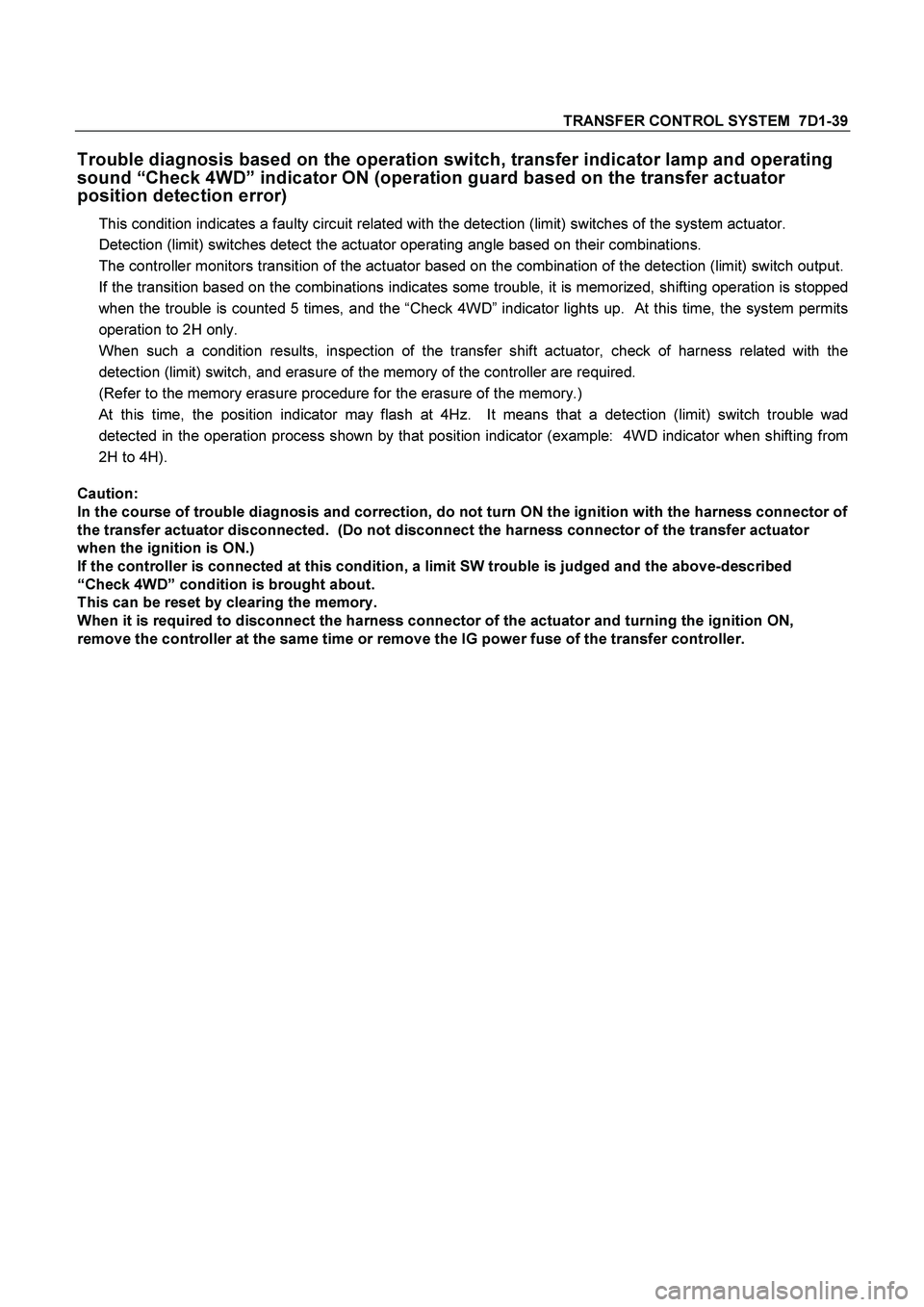
Trouble diagnosis based on the operation switch, transfer indicator lamp and operating
sound “Check 4WD” indicator ON (operation guard based on the transfer actuator
position detection error)
This condition indicates a faulty circuit related with the detection (limit) switches of the system actuator.
Detection (limit) switches detect the actuator operating angle based on their combinations.
The controller monitors transition of the actuator based on the combination of the detection (limit) switch output.
If the transition based on the combinations indicates some trouble, it is memorized, shifting operation is stopped
when the trouble is counted 5 times, and the “Check 4WD” indicator lights up. At this time, the system permits
operation to 2H only.
When such a condition results, inspection of the transfer shift actuator, check of harness related with the
detection (limit) switch, and erasure of the memory of the controller are required.
(Refer to the memory erasure procedure for the erasure of the memory.)
At this time, the position indicator may flash at 4Hz. It means that a detection (limit) switch trouble wad
detected in the operation process shown by that position indicator (example: 4WD indicator when shifting from
2H to 4H).
Caution:
In the course of trouble diagnosis and correction, do not turn ON the ignition with the harness connector of
the transfer actuator disconnected. (Do not disconnect the harness connector of the transfer actuator
when the ignition is ON.)
If the controller is connected at this condition, a limit SW trouble is judged and the above-described
“Check 4WD” condition is brought about.
This can be reset by clearing the memory.
When it is required to disconnect the harness connector of the actuator and turning the ignition ON,
remove the controller at the same time or remove the IG power fuse of the transfer controller.
Page 3668 of 4264

7D1-42 TRANSFER CONTROL SYSTEM
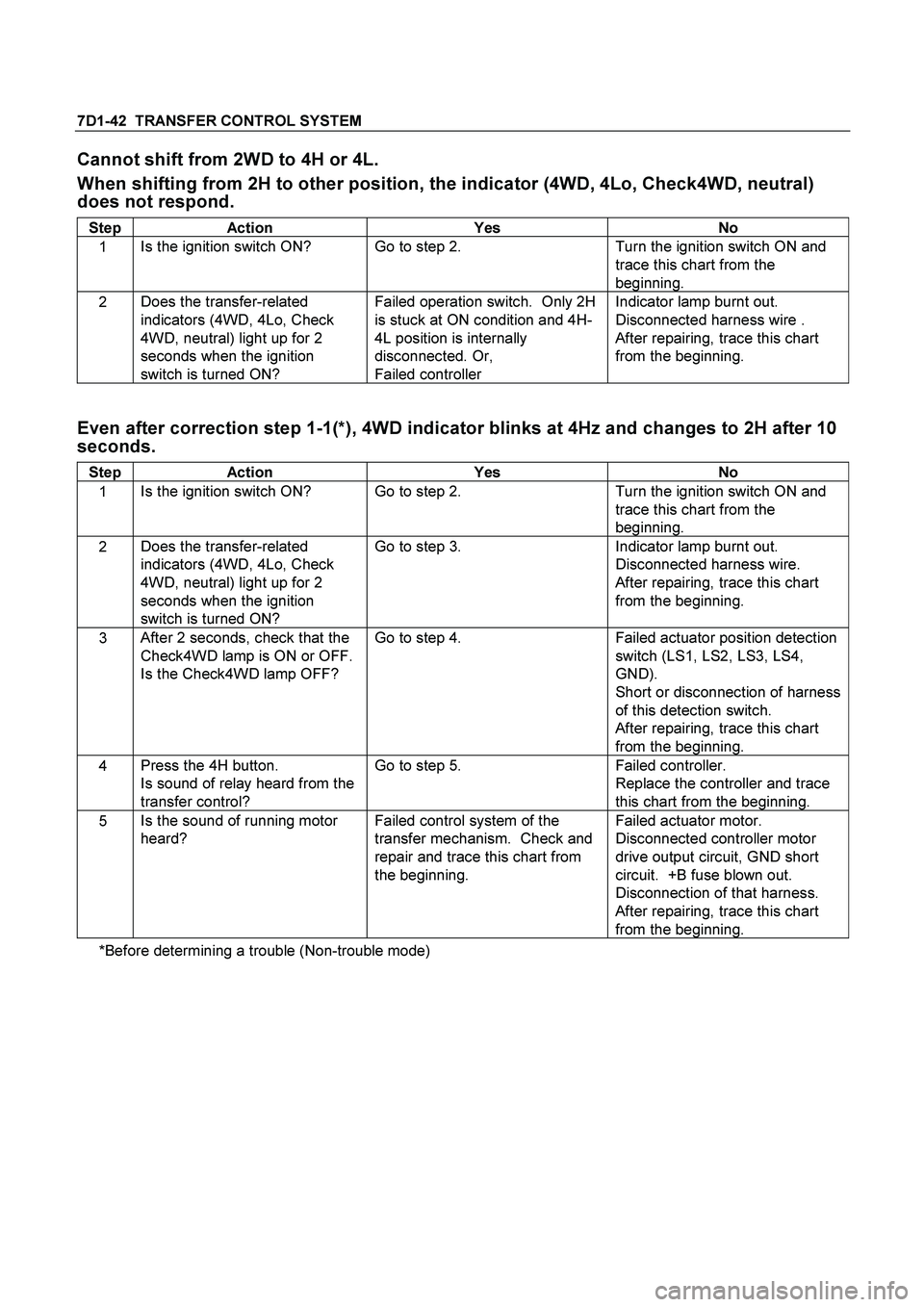
Cannot shift from 2WD to 4H or 4L.
When shifting from 2H to other position, the indicator (4WD, 4Lo, Check4WD, neutral)
does not respond.
Step Action Yes No
1 Is the ignition switch ON? Go to step 2. Turn the ignition switch ON and
trace this chart from the
beginning.
2 Does the transfer-related
indicators (4WD, 4Lo, Check
4WD, neutral) light up for 2
seconds when the ignition
switch is turned ON? Failed operation switch. Only 2H
is stuck at ON condition and 4H-
4L position is internally
disconnected. Or,
Failed controller Indicator lamp burnt out.
Disconnected harness wire .
After repairing, trace this chart
from the beginning.
Even after correction step 1-1(*), 4WD indicator blinks at 4Hz and changes to 2H after 10
seconds.
Step Action Yes No
1 Is the ignition switch ON? Go to step 2. Turn the ignition switch ON and
trace this chart from the
beginning.
2 Does the transfer-related
indicators (4WD, 4Lo, Check
4WD, neutral) light up for 2
seconds when the ignition
switch is turned ON? Go to step 3. Indicator lamp burnt out.
Disconnected harness wire.
After repairing, trace this chart
from the beginning.
3 After 2 seconds, check that the
Check4WD lamp is ON or OFF.
Is the Check4WD lamp OFF? Go to step 4. Failed actuator position detection
switch (LS1, LS2, LS3, LS4,
GND).
Short or disconnection of harness
of this detection switch.
After repairing, trace this chart
from the beginning.
4 Press the 4H button.
Is sound of relay heard from the
transfer control? Go to step 5. Failed controller.
Replace the controller and trace
this chart from the beginning.
5 Is the sound of running motor
heard? Failed control system of the
transfer mechanism. Check and
repair and trace this chart from
the beginning. Failed actuator motor.
Disconnected controller motor
drive output circuit, GND short
circuit. +B fuse blown out.
Disconnection of that harness.
After repairing, trace this chart
from the beginning.
*Before determining a trouble (Non-trouble mode)
Page 3670 of 4264
7D1-44 TRANSFER CONTROL SYSTEM
After operation, indicator of target position blinks for 1.5 sec. at 2Hz, return to 2H
condition (4WD indicator going out)
Step Action Yes No
1 Keep to press the 4H button
(about 10 seconds).
Does the 4WD indicator blink at
2Hz for 15 seconds and then
blink at 4Hz? Failed actuator motor.
Disconnection of controller motor
drive output circuit, or GND short.
+B fuse blown out.
Disconnection of that harness.
After repairing, trace this chart
from the beginning. Go to step 2.
2 Press the 4H button.
Is the sound of relay heard from
the transfer controller? Go to step 3. Failed controller.
Replace the controller and trace
this chart from the beginning.
3 Is the sound of running motor
heart? Failed control system of the
transfer mechanism. Check and
repair and trace this chart from
the beginning. Failed actuator motor.
Disconnection or GND short of
controller motor drive output
circuit.
After repairing, trace this chart
from the beginning.