Page 609 of 4264
CLUTCH 7C-7
SLAVE CYLINDER
6VE1
A07RS005
4J
C24SE
RTW47CSF000301
The slave cylinder converts hydraulic energy into mechanical energy.
Hydraulic fluid supplied by the master cylinder moves the slave cylinder piston to actuate the shift fork.
The mechanical energy produced by the slave cylinder is directly proportional to the diameters of the master
cylinder and the slave cylinder.
A bleeder screw is provided to bleed the slave cylinder.
Page 613 of 4264
CLUTCH 7C-11
C24SE
RTW37CMF000101
The pressure plate assembly consists of the clutch cover, the pressure plate with diaphragm spring.
Operating the clutch pedal causes the pressure plate to move in an axial direction to engage and disengage the
clutch.
Page 616 of 4264
7C-14 CLUTCH
C24SE
RTW37CSF0003
The driven plate assembly consists of the plate and the facing.
The plate consists of the clutch center, the cushioning plate and the torsion springs.
The facing is riveted to both sides of the cushioning plate.
The cushioning plate provides a longer service life by minimizing wear and vibration at the clutch contact surfaces.
Page 620 of 4264
7C-18 CLUTCH
C24SE
N�
m (kgf�
m/lb ft)
RTW37CLF000301
Page 624 of 4264
7C-22 CLUTCH
Important Operations - Removal
1. Transmission Assembly
Refer to “MANUAL TRANSMISSION” of section 7B and 7B1
for “REMOVAL AND INSTALLATION” procedure.
2. Clutch Pressure Plate Assembly
3. Driven Plate Assembly
(1) Use the clutch pilot aligner
1 to prevent the driven plate
assembly
2 from falling free.
Clutch Pilot Aligner : 5-85253-001-0
(2) Loosen the clutch cover bolts in the numerical order shown
in the illustration.
(3) Remove the pressure plate assembly
3 from the flywheel.
(4) Remove the driven plate from the flywheel.
201RS017
220RW088-X
4. Release Bearing (6VE1)
5. Shift Fork (6VE1)
(1) Remove the release bearing (1) from the transmission
case.
(2) Remove the shift fork snap pin (2).
(3) Remove the shift fork pin and shift fork (3) from the fulcrum
bridge.
6VE1 4JH1-TC, C24SE
Page 627 of 4264
CLUTCH 7C-25
(4) Clean the pressure plate surfaces.
(5) Align the pressure plate assembly
4 with the flywheel
knock pin
5.
(6) Install the pressure plate assembly to the flywheel.
(7) Tighten the clutch cover bolts a little at a time in the
numerical order shown in the illustration.
Clutch Cover Bolt Torque N�
m (kgf�
m/lb�
ft)
18 �
3 (1.8 �
0.3 / 13.0 �
2.2)
201RS017
(8) Remove the clutch pilot aligner.
Note:
Do not strike the clutch pilot aligner with a hammer to
remove it.
4JH1-TC, C24SE
6VE1
Page 629 of 4264

CLUTCH 7C-27
201R300011
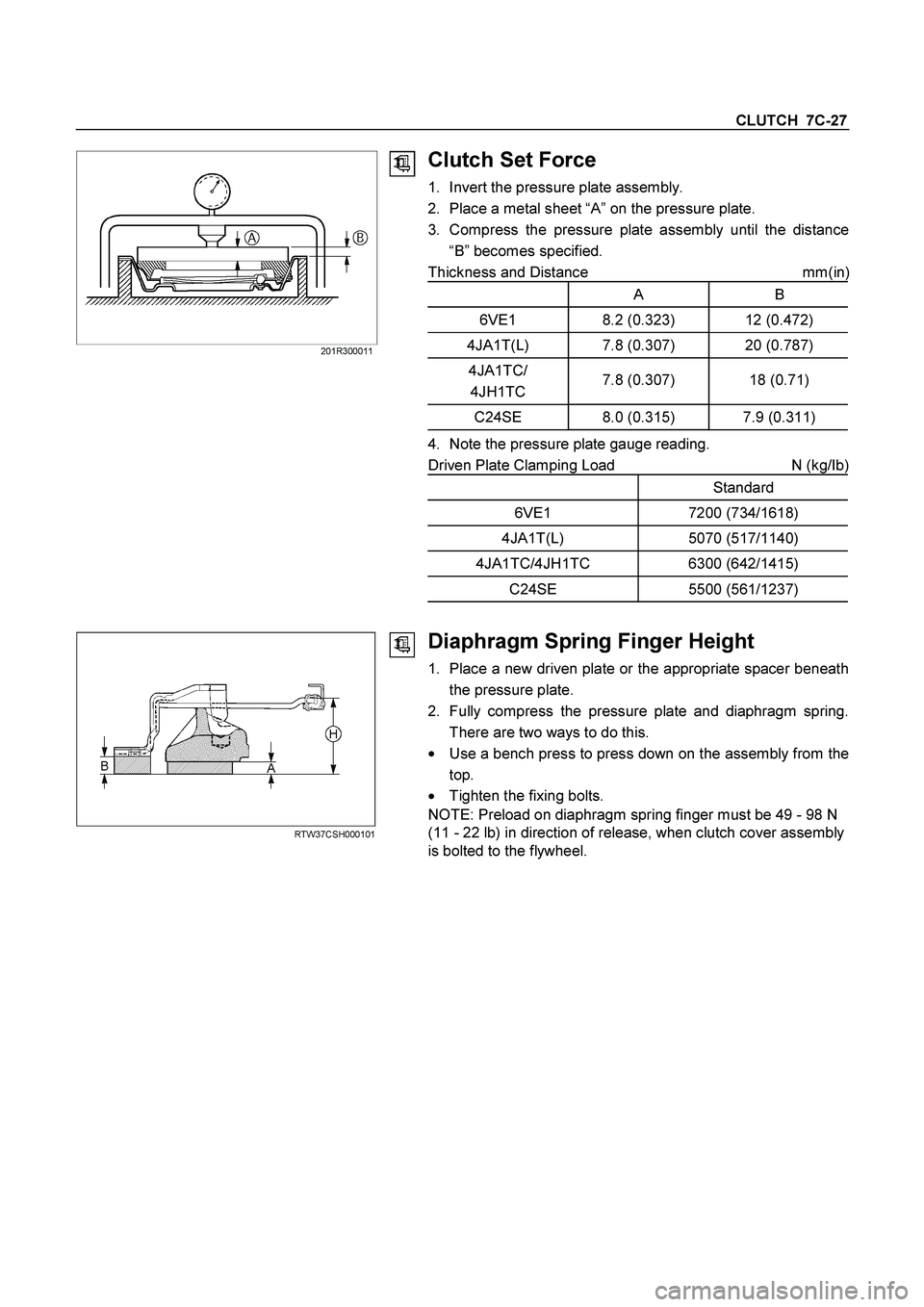
Clutch Set Force
1. Invert the pressure plate assembly.
2. Place a metal sheet “A” on the pressure plate.
3. Compress the pressure plate assembly until the distance
“B” becomes specified.
Thickness and Distance mm(in
)
A B
6VE1 8.2 (0.323) 12 (0.472)
4JA1T(L) 7.8 (0.307) 20 (0.787)
4JA1TC/
4JH1TC 7.8 (0.307) 18 (0.71)
C24SE 8.0 (0.315) 7.9 (0.311)
4. Note the pressure plate gauge reading.
Driven Plate Clamping Load N (kg/Ib)
Standard
6VE1 7200 (734/1618)
4JA1T(L) 5070 (517/1140)
4JA1TC/4JH1TC 6300 (642/1415)
C24SE 5500 (561/1237)
RTW37CSH000101
Diaphragm Spring Finger Height
1. Place a new driven plate or the appropriate spacer beneath
the pressure plate.
2. Fully compress the pressure plate and diaphragm spring.
There are two ways to do this.
�
Use a bench press to press down on the assembly from the
top.
� Tighten the fixing bolts.
NOTE: Preload on diaphragm spring finger must be 49 - 98 N
(11 - 22 lb) in direction of release, when clutch cover assembly
is bolted to the flywheel.
Page 630 of 4264
7C-28 CLUTCH
3. Measure the spring height from base to spring tip "H". If the
measured value exceeds the specified limit, the pressure
plate assembly must be replaced.
Spacer Thickness mm(in)
A B
6VE1 8.2 (0.323) 12 (0.472)
4JA1T(L) 7.8 (0.307) 20 (0.787)
4JA1TC/
4JH1TC 7.8 (0.307) 18 (0.71)
C24SE 8.0 (0.315) 7.9 (0.311)
Finger Height
6VE1 49.9-51.9 (1.96-2.04)
4JA1T(L) 31-33 (1.22-1.30)
4JA1TC/
4JH1TC 39-41 (1.54-1.61)
C24SE 39-41 (1.54-1.61)