Page 631 of 4264

1. Visually check the release bearing for excessive play, noise
and breakage.
2. If any of these conditions are discovered, the release
bearing must")
CLUTCH 7C-29
201RS011
Release Bearing (6VE1)
1. Visually check the release bearing for excessive play, noise
and breakage.
2. If any of these conditions are discovered, the release
bearing must be replaced.
201RW010-X
3. When replacing the release bearing (3), replace both the
wedge collar (2) and wire ring (1) at the same time.
201RS013
Wedge Collar
1. Visually check the surfaces of the wedge collar making
contact with the release bearing for excessive wear and
damage.
2. Replace any exhibiting excessive wear or damage.
201RS014
Shift Fork
1. Visually check the surfaces of the shift fork making contact
with the release bearing for excessive wear and damage.
2. Remove any minor stepping or abrasion from shift fork with
an oil stone.
3. Replace any exhibiting excessive wear or damage.
Release Bearing (4J, C24SE)
1. Visually inspect the surfaces of the release bearing making
contact with the shift fork for excessive wear and damage.
Replace any exhibiting excessive wear or damage.
2. Apply multi-purpose type grease (NLGI No.2 or No.3) to
contact surface between the release bearing and the shift
fork. (Do not apply grease to the sleeve inner face.)
Page 633 of 4264

CLUTCH 7C-31
Driven Plate Splined Hub Spline Wear
1. Clean the driven plate splined hub.
2. Install the driven plate to the transmission top gear shaf
t
spline.
3. Set a surface gauge to the driven plate outside
circumference.
4. Slowly turn the driven plate counterclockwise.
Measure the spline rotation play as you turn the driven
plate.
If the measured value exceeds the specified limit, the driven
plate assembly must be replaced.
Driven Plate Splined Hub Spline Wear mm(in)
Standard Limit
0.5 (0.020) 1.0 (0.039)
Rivet Head Depression
Use a depth gauge or a straight edge with steel rule to
measure the rivet head depression
1 from the facing surface
2.
Be sure to measure the rivet head depression on both sides of
the driven plate.
If the measured value is less than the specified limit, the facing
must be replaced.
Rivet Head Depression mm(in)
Standard
Fly wheel side P/Plate side Limit
4J 1.35-1.95
(0.053-0.077) 1.65-2.25
(0.065-0.089) 0.2
(0.008)
6VE1
C24SE 1.65-2.25
(0.065-0.089) 1.65-2.25
(0.065-0.089) 0.2
(0.008)
Page 637 of 4264
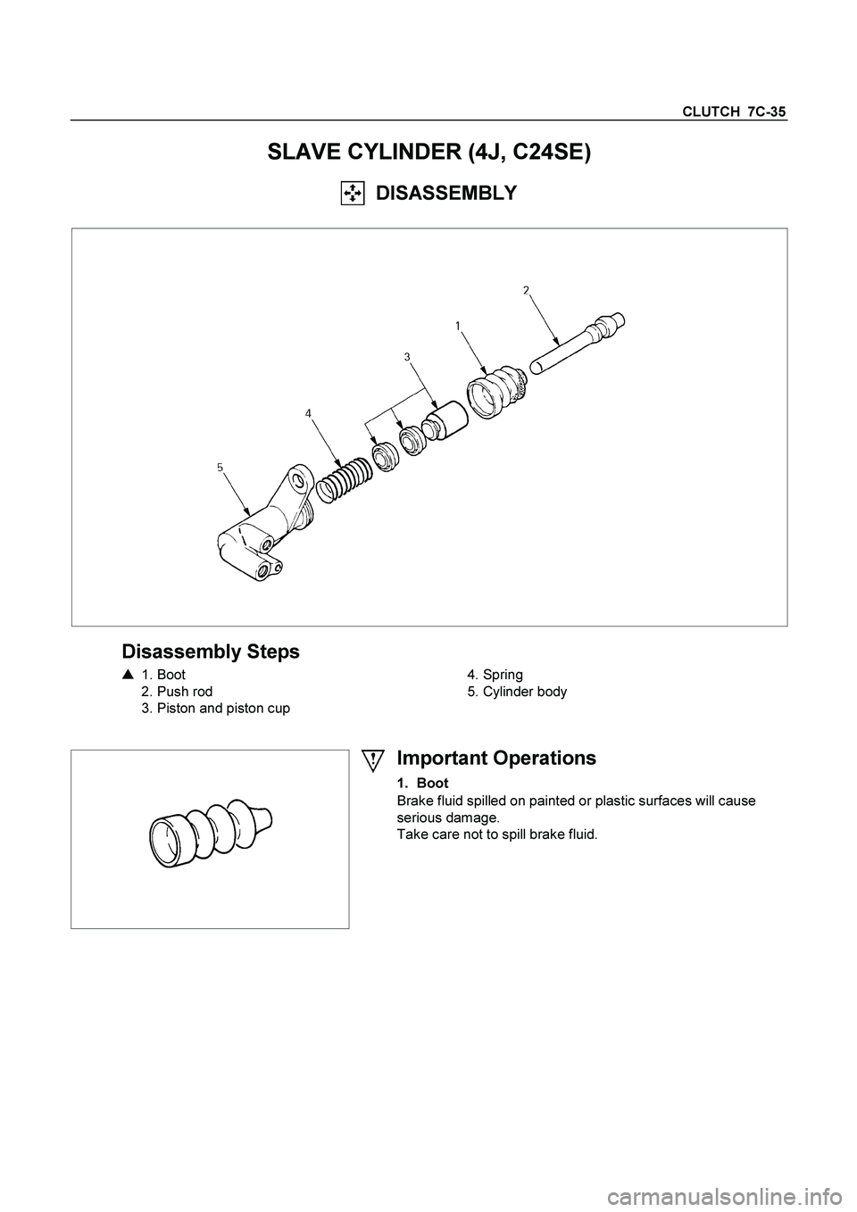
CLUTCH 7C-35
SLAVE CYLINDER (4J, C24SE)
DISASSEMBLY
Disassembly Steps
�
1. Boot
2. Push rod
3. Piston and piston cup
4. Spring
5. Cylinder body
Important Operations
1. Boot
Brake fluid spilled on painted or plastic surfaces will cause
serious damage.
Take care not to spill brake fluid.
Page 660 of 4264
 .................................... 8A- 31
Fuse Location ............................................")
8A-2 ELECTRICAL-BODY AND CHASSIS
PAGE
Fuse and Slow Blow Fuse Location (Relay and Fuse Box) .................................... 8A- 31
Fuse Location ............................................................................................................. 8A- 33
Diode Location ........................................................................................................... 8A- 34
Fuse Block Circuit ...................................................................................................... 8A- 35
Fuse Block Circuit (C24SE) ....................................................................................... 8A- 35
Fuse Block Circuit (6VE1) ......................................................................................... 8A- 37
Fuse Block Circuit (4JA1-TC/4JH1-TC) - RHD ......................................................... 8A- 39
Fuse Block Circuit (4JA1-TC/4JH1-TC) – LHD ......................................................... 8A- 41
Fuse Block Circuit (4JH1-L) ...................................................................................... 8A- 43
Grounding Point ............................................................................................................. 8A- 45
Ground Point .............................................................................................................. 8A- 45
Ground Point Location .............................................................................................. 8A- 61
Main Cable harness Routing .......................................................................................... 8A- 63
C24SE / 6VE1 / 4JA1-L / 4JH1-TC .............................................................................. 8A- 63
Instrument Harness .................................................................................................... 8A- 71
System Repair .................................................................................................................8A- 73
Start and Charging ..................................................................................................... 8A- 73
Engine Control Module (ECM) ................................................................................... 8A- 89
Exhaust Gas Recalculation (EGR): 4JA1-L Only ...................................................... 8A- 109
Lighting ....................................................................................................................... 8A- 114
Front Fog Light ........................................................................................................... 8A- 136
Rear Fog Light ............................................................................................................ 8A- 144
Head Light Leveling ................................................................................................... 8A- 149
Illumination ................................................................................................................. 8A- 154
Hazard Warning Flasher, Turn Signal Light, Back Up Light,
Horn and Stop Light ................................................................................................. 8A- 161
Dome Light, Spot Light and Warning Buzzer .......................................................... 8A- 181
Windshield Wiper and Washer .................................................................................. 8A- 196
Transmission Control Module (TCM) ....................................................................... 8A- 214
Meter, Warning Light and Indicator Light ................................................................ 8A- 223
Heater and Air Conditioning ...................................................................................... 8A- 281
Power Door Lock ....................................................................................................... 8A- 293
Page 686 of 4264
8A-28 ELECTRICAL-BODY AND CHASSIS
RELAY LOCATION (RELAY AND FUSE BOX)
RELAY & FUSE BOX
RHD
NO. RELAY (C24SE) RELAY (6VE1) RELAY
(4JA1-TC/4JH1-TC)RELAY (4JA1-L)
X-1 RELAY; TAIL LIGHT
� � �
X-2 RELAY; FUEL PUMP
� RELAY; FRT FOG RELAY; FRT FOG
LIGHT
X-3 RELAY; HORN
� � �
X-4 RELAY; DIMMER
� � �
X-5 RELAY; FOG LIGHT
� RELAY; GLOW RELAY; GLOW
X-6 RELAY; STARTER
� RELAY; COND, FAN RELAY; CSD
X-7 RELAY; COND, FAN
� RELAY; RR FOG
�
X-8
� � RELAY; STARTER RELAY; STARTER
X-9 RELAY; HAZARD-RH
� � �
X-10 RELAY; HAZARD-LH
� � �
X-11 RELAY; HEATER
� � �
X-12 RELAY; HEAD
LIGHT � � �
X-13
� RELAY; ECM MAIN
� RELAY; COND, FAN
X-14 RELAY; A/C COMP
� � �
X-15 RELAY; THERMO
� � �
Page 687 of 4264
ELECTRICAL-BODY AND CHASSIS 8A-29
RELAY LOCATION (RELAY AND FUSE BOX)
RELAY & FUSE BOX
LHD
NO. RELAY (C24SE) RELAY (6VE1) RELAY
(4JA1-TC 4JH1-TC)RELAY (4JA1-L)
X-1 RELAY; TAIL LIGHT
� � �
X-2 RELAY; FUEL PUMP
� RELAY; FRT FOG RELAY; FRT FOG
LIGHT
X-3 RELAY; HORN
� � �
X-4 RELAY; DIMMER
� � �
X-5 RELAY; FRT FOG
LIGHT RELAY; FOG LIGHT RELAY; GLOW RELAY; GLOW
X-6 RELAY; STARTER
� RELAY; COND, FAN RELAY; CSD
X-7 RELAY; COND, FAN
� RELAY; RR FOG
�
X-8
� � RELAY; STARTER
�
X-9
� � SHORT
CONNECTOR
(with cooler) �
X-10
� � � �
X-11 RELAY; HEATER
� � �
X-12 RELAY; HEAD
LIGHT � � �
X-13
� RELAY; ECM MAIN
� RELAY; COND, FAN
X-14 RELAY; A/C COMP
� � �
X-15 RELAY; THERMO
� � �
Page 688 of 4264
8A-30 ELECTRICAL-BODY AND CHASSIS
RELAY LOCATION
(CABIN)
RELAY
Connector No. B-7 B-8 B-40
C24SE
6VE1
4JA1-TC, 4JH1-TC
4JA1-L REAR DEFOGGER
POWER WINDOW ACC SOCKET
Page 689 of 4264

RELAY & FUSE BOX
RHD
FUSE �
ENGINE MODEL
FUSE NO. C24SE 6VE1 4JA1-TC / 4JH1-TC4JA1-L
EB-1 15A EC")
ELECTRICAL-BODY AND CHASSIS 8A-31
FUSE AND SLOW BLOW FUSE LOCATION (RELAY AND FUSE BOX)
RELAY & FUSE BOX
RHD
FUSE �
ENGINE MODEL
FUSE NO. C24SE 6VE1 4JA1-TC / 4JH1-TC4JA1-L
EB-1 15A ECM 20A ECM 10A ECM �
EB-2 �
10A ECM (B) 10A RR FOG �
EB-3 15A FRT FOG
10A TCM 15A FRT FOG �
EB-4 10A ACG (S) 15A FRT FOG � 10A ACG (S)
EB-5 10A ILLUMI � 10A ILLUMI & TAIL-RH10A ILLUMI
EB-6 10A TAIL � 10A TAIL-LH 10A TAIL
EB-7 10A H/LIGHT-RH � 10A H/LIGHT RH-LOW10A H/LIGHT RH
EB-8 10A H/LIGHT-LH � 10A H/LIGHT LH-LOW10A H/LIGHT LH
EB-9 20A FUEL PUMP 10A O2 SENSOR 10A TRA ILER �
EB-10 10A O2 SENSOR 20A FUEL PUMP 10A AC G (S) �
EB-11 � � 10A H/LIGHT RH-HIGH �
EB-12 � � 10A H/LIGHT LH-HIGH�
EB-13 10A A/C �
� �
EB-14 10A 4WD
10A 4WD � �
EB-15 10A HORN � � �
EB-16 15A HAZARD 10A HAZARD � �
SLOW BLOW FUSE
ENGINE MODEL
FUSE NO. C24SE 6VE1 4JA1-TC / 4JH1-TC4JA1-L
SBF-1 100A MAIN �
80A MAIN �
SBF-2 � �
20A COND, FAN �
SBF-3 � �
60A GLOW 20A COND, FAN
SBF-4 20A COND, FAN �
30A ECM 50A GLOW
SBF-5 40A IG 1 � � �
SBF-6 �
40A ABS-1 � �
SBF-7 �
30A ABS-2 � �
SBF-8 30A BLOWER � � �
SBF-9 50A IG 2 � � �

RELAY & FUSE BOX
RHD
NO. RELAY (C24SE) RELAY (6VE1) RELAY
(4JA1-TC/4JH1-TC)R")

RELAY & FUSE BOX
LHD
NO. RELAY (C24SE) RELAY (6VE1) RELAY
(4JA1-TC 4JH1-TC)R")

RELAY
Connector No. B-7 B-8 B-40
C24SE
6VE1
4JA1-TC, 4JH1-TC
4JA1-L REAR DEFOGGER
POWER WINDOW ACC SOCKET")