Page 67 of 4264
SUPPLEMENTAL RESTRAINT SYSTEM 9A-47
Main Data and Specifications
Fastener Tightening Specification
Application N�
�� �m kg�
�� �m Ft.lb
SRS control unit 7 0.7 5
Steering wheel fixing bolt 35 3.5 25
Steering column (dash panel side fixing bolts) 20 2.0 14
Steering column (Pedal bracket fixing bolt) 20 2.0 14
Steering column (Universal joint fixing bolt) 31 3.2 23
Passenger Air Bag fixing bolt & nut 8 0.8 5.8
Pretensioner seat belt bolt 55 5.6 40
Page 75 of 4264

RESTRAINT CONTROL 9A1-5
The SRS control unit displays the trouble codes by
flashing the warning lamp. Each code that is displayed
will consist of a number of flashes which represents the
tens digit, a 1.2 second pause, following by a number of
flashes which represents the ones digit of the code.
Each code is displayed one time before moving on to
the next code. After all of the codes have been
displayed, the entire code sequence will continually by
repeated until ground is removed from terminal 4 of the
DLC connector.
Two special codes exist when reading in the flash code
mode (Flash Code 12 and Flash Code 13). “Flash
Code 12” will always be the first code displayed when
the flash code mode is enable Code 12 is not an
indication of a SRS problem but an indication that the
flash code mode has been enabled. If there are no
active or history codes present, the SRS control unit will
display code 12 until ground is removed from the DLC
connector at terminal 4. “flash Code 13” will be
displayed if history codes are present. To read the
history codes a scan tool must be used.
060R300051
DATA LIST (Tech 2)
DISPLAY on Tech 2 UNIT VALUE
Driver Airbag Loop
Enabled/Disabled
Passenger Airbag Loop
Enabled/Disabled
System Voltage V 12.0
Driver Seat Belt Status
Not Backled/Backled
Page 117 of 4264
 Passenger Pretensioner Squib Circuit Voltage
Range/Performance
RTW49JLF000101
Circuit Description
When the ignition switch is turned")
RESTRAINT CONTROL 9A1-47
DTC B0059 (Flash Code 59) Passenger Pretensioner Squib Circuit Voltage
Range/Performance
RTW49JLF000101
Circuit Description
When the ignition switch is turned “ON”, the SRS
control unit will perform tests to diagnose critical
malfunctions within itself. Upon passing these tests,
“Ignition 1”, and pretensioner loop voltages are
measured to ensure they are within their respective
normal voltage ranges.
The SRS control unit monitors the voltages at “Drive
r
Pretensioner Low” terminal “41” and “Passenger
Pretensioner Low” terminal “43” to detect short to
ground/+B in the pretensioner assembly circuits.
DTC Will Set When
Neither of the air bag and the pretensioner are belt
open. “Ignition 1” is within the normal operating voltage
range. Once these conditions are met and the voltage
at “Passenger Pretensioner Low” is out of a specified
value, DTC B0059 will set. This test is run once each
ignition cycle and “Continuous Monitoring”.
Action Taken
SRS control unit turns “ON” the “AIR BAG” warning
lamp and sets a diagnostic trouble code.
Page 495 of 4264
PARKING BRAKE SYSTEM 5D-5
Front Parking Brake Cable
Front Parking Brake Cable and Associated Parts (Bench Seat)
750R300003
Legend
(1)
Shift Knob (manual transmission)
(2)
Front Floor Console
(3)
Rear Cover
(4)
Bolt
(5)
Seat Assembly
(6)
Buckle: side seat and Center Seat Belt
(7)
Seat Adjuster
Page 509 of 4264

CAB 10-1
SECTION 10
CAB
TABLE OF CONTENTS
PAGE
Windshield.......................................................................................................................... 10- 2
Rear Window Assembly .................................................................................................... 10- 7
Front Door Assembly ........................................................................................................ 10- 10
Rear Door Assembly (Crew Cab) ...................................................................................... 10- 20
Instrument Panel................................................................................................................ 10- 28
Floor Console..................................................................................................................... 10- 34
Console Box (Without Floor Console) ............................................................................. 10- 38
Headlining .......................................................................................................................... 10- 39
Interior Trim Panels ...........................................................................................................10- 44
Fuel Filler Lid Opener Lever/Cable................................................................................... 10- 55
Quarter Glass (Extend Cab) .............................................................................................. 10- 70
Font Seat ............................................................................................................................ 10- 71
Rear Seat (Crew Cab) ........................................................................................................ 10- 74
Jump Seat (Extend Cab) ................................................................................................... 10- 75
Front Seat Belt ................................................................................................................... 10- 76
Rear Seat Belt (Crew Cab) ................................................................................................ 10- 80
Rear Seat Belt (Extend Cab) ............................................................................................. 10- 84
Front Wheel Extension ...................................................................................................... 10- 87
Rear Wheel Extension ....................................................................................................... 10- 88
Tail Gate Assembly ............................................................................................................ 10- 89
Page 552 of 4264
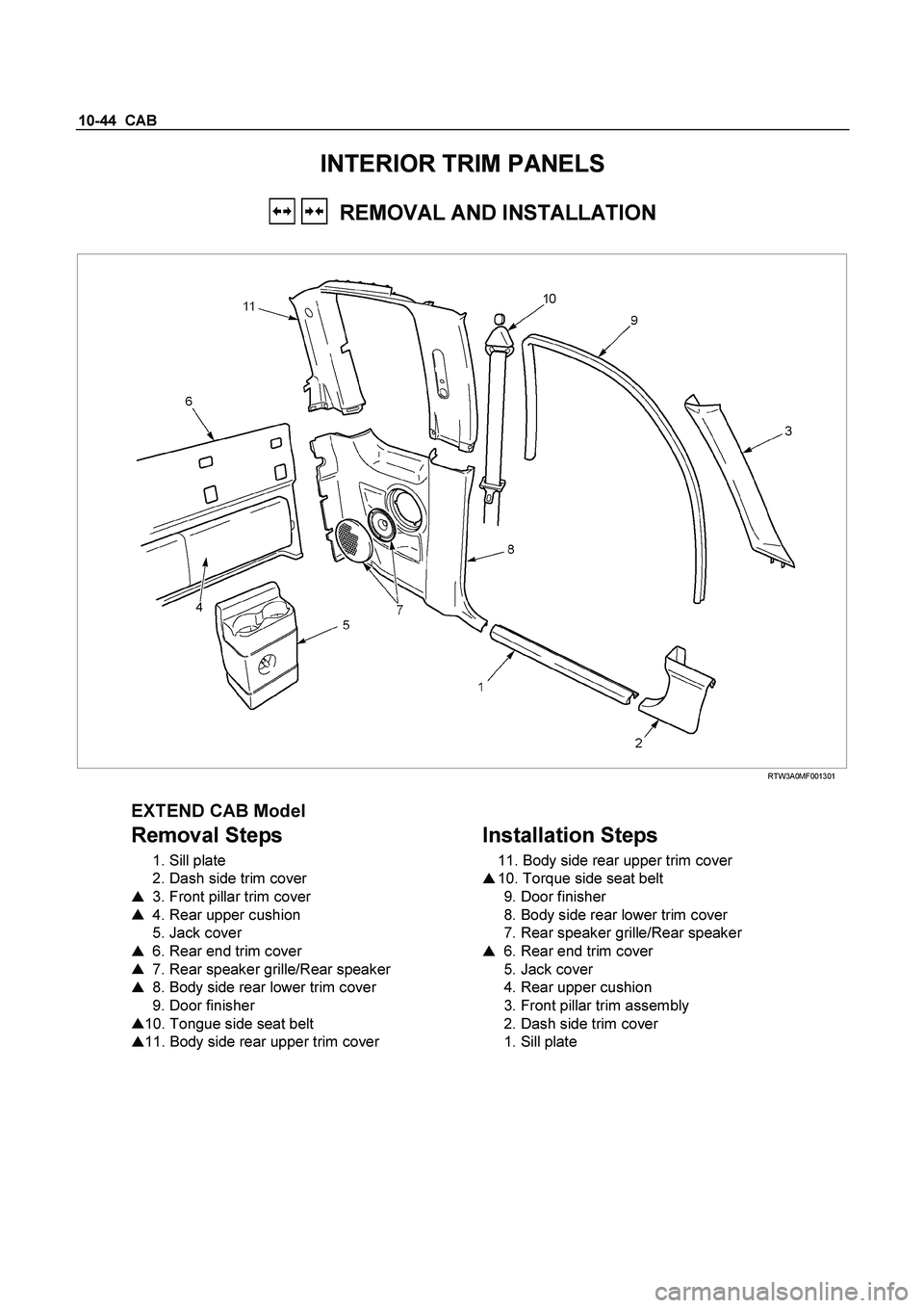
10-44 CAB
INTERIOR TRIM PANELS
REMOVAL AND INSTALLATION
RTW3A0MF001301
EXTEND CAB Model
Removal Steps
1. Sill plate
2. Dash side trim cover
� 3. Front pillar trim cover
� 4. Rear upper cushion
5. Jack cover
� 6. Rear end trim cover
� 7. Rear speaker grille/Rear speaker
� 8. Body side rear lower trim cover
9. Door finisher
� 10. Tongue side seat belt
� 11. Body side rear upper trim cover
Installation Steps
11. Body side rear upper trim cover
� 10. Torque side seat belt
9. Door finisher
8. Body side rear lower trim cover
7. Rear speaker grille/Rear speaker
� 6. Rear end trim cover
5. Jack cover
4. Rear upper cushion
3. Front pillar trim assembly
2. Dash side trim cover
1. Sill plate
Page 554 of 4264
10-46 CAB
10. Tongue Side Seat Belt
1) Pull out the adjuster knob.
RTW3A0SH000301
2) Open the through ring anchor cover and remove the
seat belt upper anchor bolt.
11. Body Side Rear Upper Trim Cover
�
Pry the trim cover clips free from the body panel.
Page 555 of 4264
CAB 10-47
Important Operations - Installation
10. Tongue Side Seat Belt
�
Tighten the seat belt upper anchor bolt to the specified
torque.
Torque N�
m (kgf�
m/lb�
ft)
40 (4.1/30)
6. Rear End Trim Cover
�
Insert the hooks on the back upper portion of trim cove
r
to the body panel.


750R300003
Legend
(1)
Shift Knob (manual transmission)
(2)
Front")
 Pull out the adjuster knob.
RTW3A0SH000301
2) Open the through ring anchor cover and remove the
seat belt upper anchor bolt.
11. Body Si")
