Page 683 of 4264
ELECTRICAL-BODY AND CHASSIS 8A-25
Light Name Rated Power
V-W Number of
Bulbs Lens
Color Remarks
W/O Tacho 5Illumination light 14-2
W/ Tacho 7White
Turn Signal 14-1.12 2 Green
High Beam 14-1.12 1 Blue
Low Fuel 14-1.12 1 Amber
A/T Oil Temp 14-1.12 1 Red
Brake system 14-1.12 1 Red
4WD 14-1.12 1 Green
Seat belt 14-1.12 1 Red
Oil pressure 14-1.12 1 Red
ABS 14-1.12 1 Amber
SEDIMENTER 14-1.12 1 Red
AIR BAG 14-1.12 1 Red
Brake 14-1.12 1 Red
Charge 14-1.12 1 Red
Check Trans 14-1.12 1 Red
Check 4WD 14-1.12 1 Red
Power drive 14-1.12 1 Amber
3rd start 14-1.12 1 Green
4L 14-1.12 1 Green
Cruise Set 14-1.12 1 Green
Check Engine 14-1.12 1 Amber
Front Fog 14-1.12 1 Green
Rear foglight 14-1. 12 1 Amber
Glow 14-1.12 1 Amber
P LED 1 Green
R LED 1 Green
N LED 1 Green
D LED 1 Green
3 LED 1 Green
2 LED 1 Green
Indicator/
Warning
light
A/T shift
indicator
L LED 1 Green
Page 1080 of 4264
8A-422 ELECTRICAL-BODY AND CHASSIS
No. Connector face No. Connector face
C-1
Gray
Side turn lamp-RH C-22
Front turn lamp-RH
C-2
Silver
Engine room-RH ground C-23
NOT USED
C-3
(6VE1)
(4JH1-TC)
INT Relay C-24
Triple pressure switch
C-4
Light-
blue
Front wiper motor C-25
NOT USED
C-5
~
C-16 NOT USED C-26
Black
Head lamp-LH
C-17
Gray
Front wiper motor C-27
Clearance lamp-LH
C-18
Clearance lamp-RH C-28
~
C-29 NOT USED
C-19
Black
Head lamp-RH C-30
BlackEngine hood switch
C-20
(6VE1)
(4JH1-TC)
Horn ; high note C-31
~
C-34 NOT USED
C-21
Black
Horn ; Low note C-35
Gray Side turn lamp-LH
Page 1086 of 4264
8A-428 ELECTRICAL-BODY AND CHASSIS
No. Connector face No. Connector face
E-1
(4JH1-TC)
White Oil pressure switch E-10
SilverEngine ground
E-2
(C24SE)
(6VE1)
Magnetic clutch E-11
(6VE1)
Neutral switch
E-3
(4JH1-TC)
Black
Magnetic clutch AC COMP E-11
(4JH1-TC)
Natural
green
Neutral switch
E-4
~
E-5 NOT USED E-12
(6VE1)
Neutral switch
E-6
(C24SE)
(6VE1)
(6VE1) Fuel injector (C24SE) E-12
(4JH1-TC)
Natural
green
Neutral switch
E-6
(4JH1-TC)
Injector pump E-13
~
E-17 NOT USED
E-7
(C24SE)
(6VE1)
(6VE1) Fuel injector (C24SE) E-18
(C24SE)
Ignition coil
E-8
(C24SE)
(6VE1)
(6VE1) Fuel injector (C24SE) E-19
(4JH1-TC)
Blue Thermo meter unit
E-9
(C24SE)
(6VE1)
(6VE1) Fuel injector (C24SE) E-20
~
E-21 NOT USED
E-9
(4JH1-TC)
Gray T.D.C sensor E-22
(4JH1-TC)
BrownTPS 1 main
Page 1091 of 4264
ELECTRICAL-BODY AND CHASSIS 8A-433
No. Connector face No. Connector face
H-1
White
Battery (+) ~ Engine room H-10
WhiteINST ~ Front Door-RH
H-2
NOT USED H-11
NOT USED
H-3
(6VE1,
4JH1-TC)
White Battery (+) ~ Engine room H-12
BlackINST ~ Roof
H-4
(C24SE)
White Engine room ~ Mission H-13
WhiteINST ~ Door -LH
H-4
(6VE1,
4JA1-TC,
4JH1-TC)
White
Engine ~ Engine room H-14
WhiteRear body ~ Rear door-LH
H-5
NOT USED H-15
White
Engine room ~ Chassis
H-6
White
Engine room ~ INST H-16
WhiteRear body ~ Rear door-RH
H-7
White
Engine room ~ INST H-17
WhiteChassis ~ License plate lamp
H-8
NOT USED H-18
White
Engine room ~ INST
H-9
Blue
Engine room ~ Chassis H-19
~
H-21 NOT USED
Page 1163 of 4264
ENGINE MECHANICAL 6A – 23
LOCTITE APPLICATION PROCEDURE
LOCTITE Type LOCTITE Color Application Steps
LOCTITE 242 Blue
LOCTITE 262 Red
LOCTITE 270 Green
LOCTITE 271 Red 1. Completely remove all lubricant and moisture from the bolts and the
female threaded surfaces of the parts to be joined.
The surfaces must be perfectly dry.
2. Apply LOCTITE to the bolts.
3. Tighten the bolts to the specified torque.
4. Wait at least one hour before continuing the installation procedure.
LOCTITE 515 Violet 1. Completely remove lubricant and moisture from the connecting
surfaces.
The surfaces must be perfectly dry.
2. Apply a 2.0 – 2.5 mm bead of LOCTITE to one of the connecting
surfaces.
There must be no gaps in the bead.
3. Tighten the bolts to the specified torque.
4. Let the joined parts set for at least thirty minutes.
Page 1224 of 4264

6A – 84 ENGINE MECHANICAL
015RY00017
RTW46ASH002501
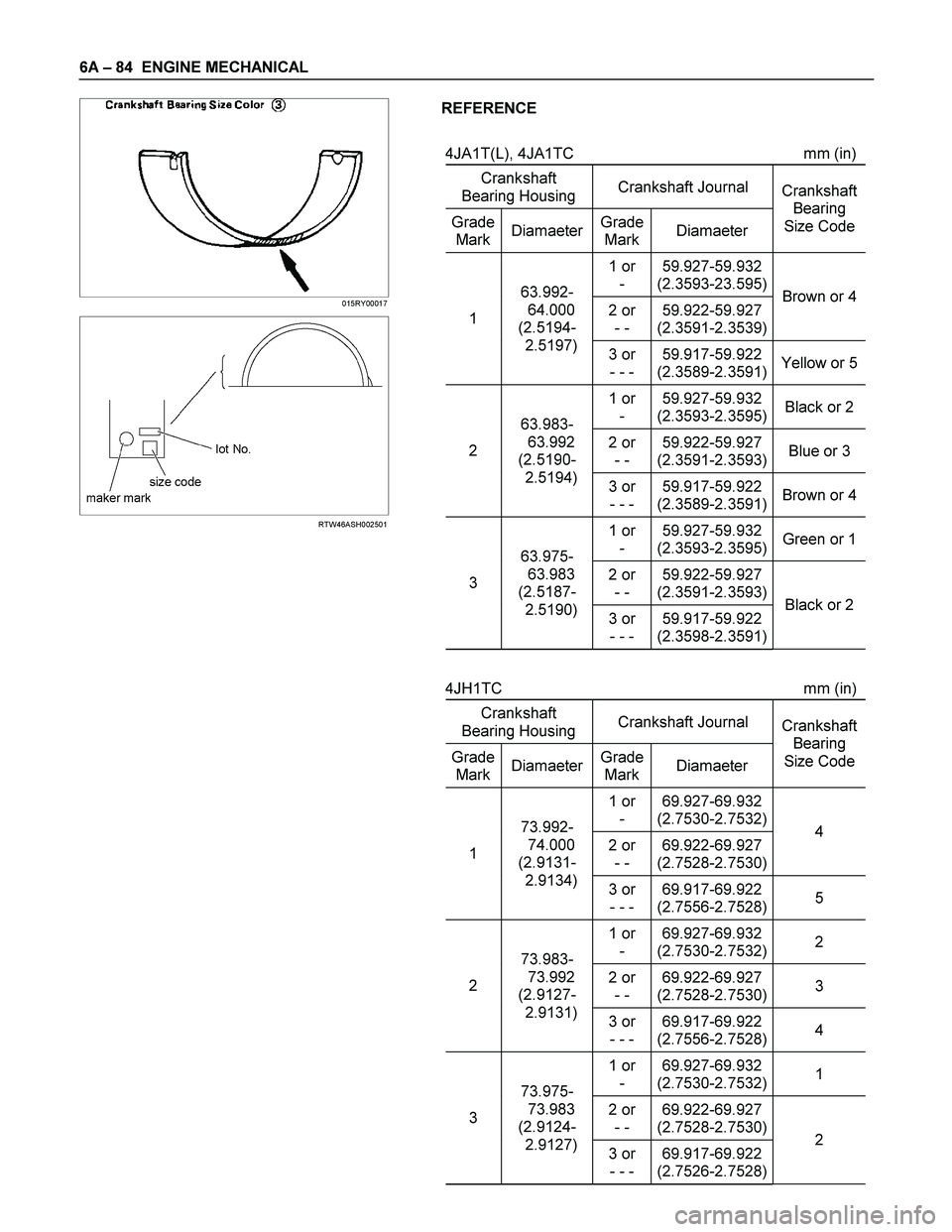
REFERENCE
4JA1T(L), 4JA1TC mm (in)
Crankshaft
Bearing Housing Crankshaft Journal
Grade
MarkDiamaeterGrade
MarkDiamaeter Crankshaft
Bearing
Size Code
1 or
- 59.927-59.932
(2.3593-23.595)
2 or
- - 59.922-59.927
(2.3591-2.3539)Brown or 41 63.992-
64.000
(2.5194-
2.5197)
3 or
- - - 59.917-59.922
(2.3589-2.3591)Yellow or 5
1 or
- 59.927-59.932
(2.3593-2.3595)Black or 2
2 or
- - 59.922-59.927
(2.3591-2.3593)Blue or 3 2 63.983-
63.992
(2.5190-
2.5194)
3 or
- - - 59.917-59.922
(2.3589-2.3591)Brown or 4
1 or
- 59.927-59.932
(2.3593-2.3595)Green or 1
2 or
- - 59.922-59.927
(2.3591-2.3593)3 63.975-
63.983
(2.5187-
2.5190)
3 or
- - - 59.917-59.922
(2.3598-2.3591)Black or 2
4JH1TC mm (in)
Crankshaft
Bearing Housing Crankshaft Journal
Grade
MarkDiamaeterGrade
MarkDiamaeter Crankshaft
Bearing
Size Code
1 or
- 69.927-69.932
(2.7530-2.7532)
2 or
- - 69.922-69.927
(2.7528-2.7530)4 1 73.992-
74.000
(2.9131-
2.9134)
3 or
- - - 69.917-69.922
(2.7556-2.7528)5
1 or
- 69.927-69.932
(2.7530-2.7532)2
2 or
- - 69.922-69.927
(2.7528-2.7530)3 2 73.983-
73.992
(2.9127-
2.9131)
3 or
- - - 69.917-69.922
(2.7556-2.7528)4
1 or
- 69.927-69.932
(2.7530-2.7532)1
2 or
- - 69.922-69.927
(2.7528-2.7530)3 73.975-
73.983
(2.9124-
2.9127)
3 or
- - - 69.917-69.922
(2.7526-2.7528)2
Page 1381 of 4264

4JA1/4JH1 ENGINE DRIVEABILITY AND EMISSIONS 6E–9
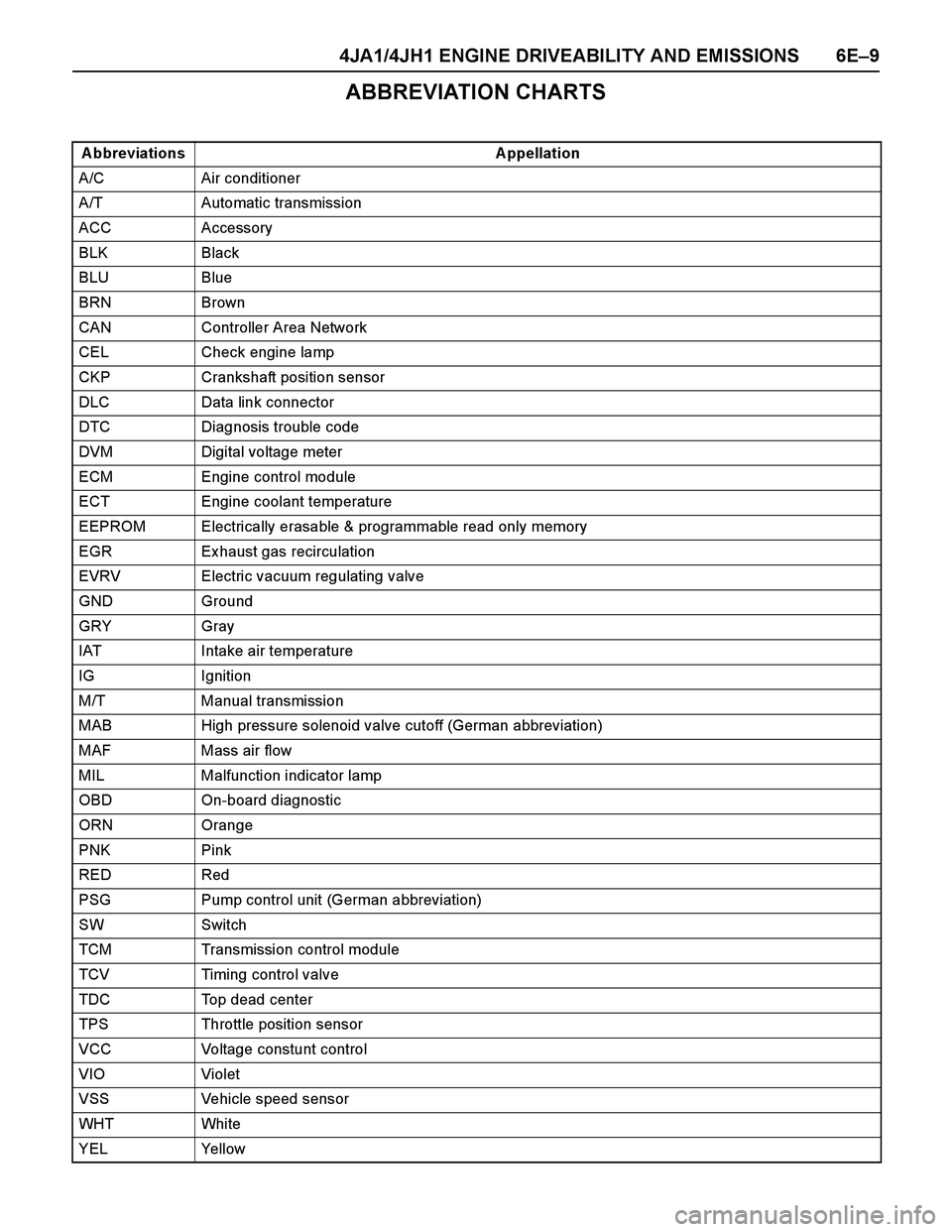
ABBREVIATION CHARTS
A bbreviations A ppellation
A/C Air conditioner
A/T Automatic transmission
ACC Accessory
BLK Black
BLU Blue
BRN Brown
CAN Controller Area Network
CEL Check engine lamp
CKP Crankshaft position sensor
DLC Data link connector
DTC Diagnosis trouble code
DVM Digital voltage meter
ECM Engine control module
ECT Engine coolant temperature
EEPROM Electrically erasable & programmable read only memory
EGR Ex haust gas recirculation
EVRV Electric vacuum regulating valve
GND Ground
GRY Gray
IAT Intake air temperature
IG Ignition
M/T Manual transmission
MAB High pressure solenoid valve cutoff (German abbreviation)
MAF Mass air flow
MIL Malfunction indicator lamp
OBD On-board diagnostic
ORN Orange
PNK Pink
RED Red
PSG Pump control unit (German abbreviation)
SW Switch
TCM Transmission control module
TCV Timing control valve
TDC Top dead center
TPS Throttle position sensor
VCC Voltage constunt control
VIO Violet
VSS Vehicle speed sensor
WHT Whi te
YEL Yellow
Page 1899 of 4264

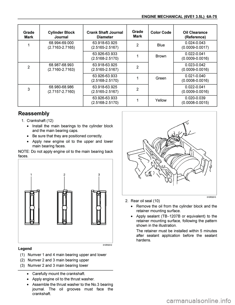
ENGINE MECHANICAL (6VE1 3.5L) 6A-75
Grade
Mark
Cylinder Block
Journal
Crank Shaft Journal
Diameter
Grade
Mark
Color Code
Oil Clearance
(Reference)
1 68.994-69.000
(2.7163-2.7165) 63.918-63.925
(2.5165-2.5167) 2 Blue 0.024-0.043
(0.0009-0.0017)
63.926-63.933
(2.5168-2.5170) 1 Brown 0.022-0.041
(0.0009-0.0016)
2 68.987-68.993
(2.7160-2.7163) 63.918-63.925
(2.5165-2.5167) 2 0.023-0.042
(0.0009-0.0016)
63.926-63.933
(2.5168-2.5170) 1 Green 0.021-0.040
(0.0008-0.0016)
3 68.980-68.986
(2.7157-2.7160) 63.918-63.925
(2.5165-2.5167) 2 0.022-0.041
(0.0009-0.0016)
63.926-63.933
(2.5168-2.5170) 1 Yellow 0.020-0.039
(0.0008-0.0015)
Reassembly
1. Crankshaft (12)
� Install the main bearings to the cylinder block
and the main bearing caps.
� Be sure that they are positioned correctly.
�
Apply new engine oil to the upper and lower
main bearing faces.
NOTE: Do not apply engine oil to the main bearing back
faces.
015RS012
Legend
(1) Numver 1 and 4 main bearing upper and lower
(2) Numver 2 and 3 main bearing upper
(3) Numver 2 and 3 main bearing lower
� Carefully mount the crankshaft.
� Apply engine oil to the thrust washer.
�
Assemble the thrust washer to the No.3 bearing
journal. The oil grooves must face the
crankshaft.
015RS013
2. Rear oil seal (10)
� Remove the oil from the cylinder block and the
retainer mounting surface.
� Apply sealant (TB�1207B or equivalent) to the
retainer mounting surface, following the pattern
shown in the illustration.
The retainer must be installed within 5 minutes
after sealant application before the sealan
t
hardens.