Page 3617 of 4264

TRANSFER CASE 7D-29
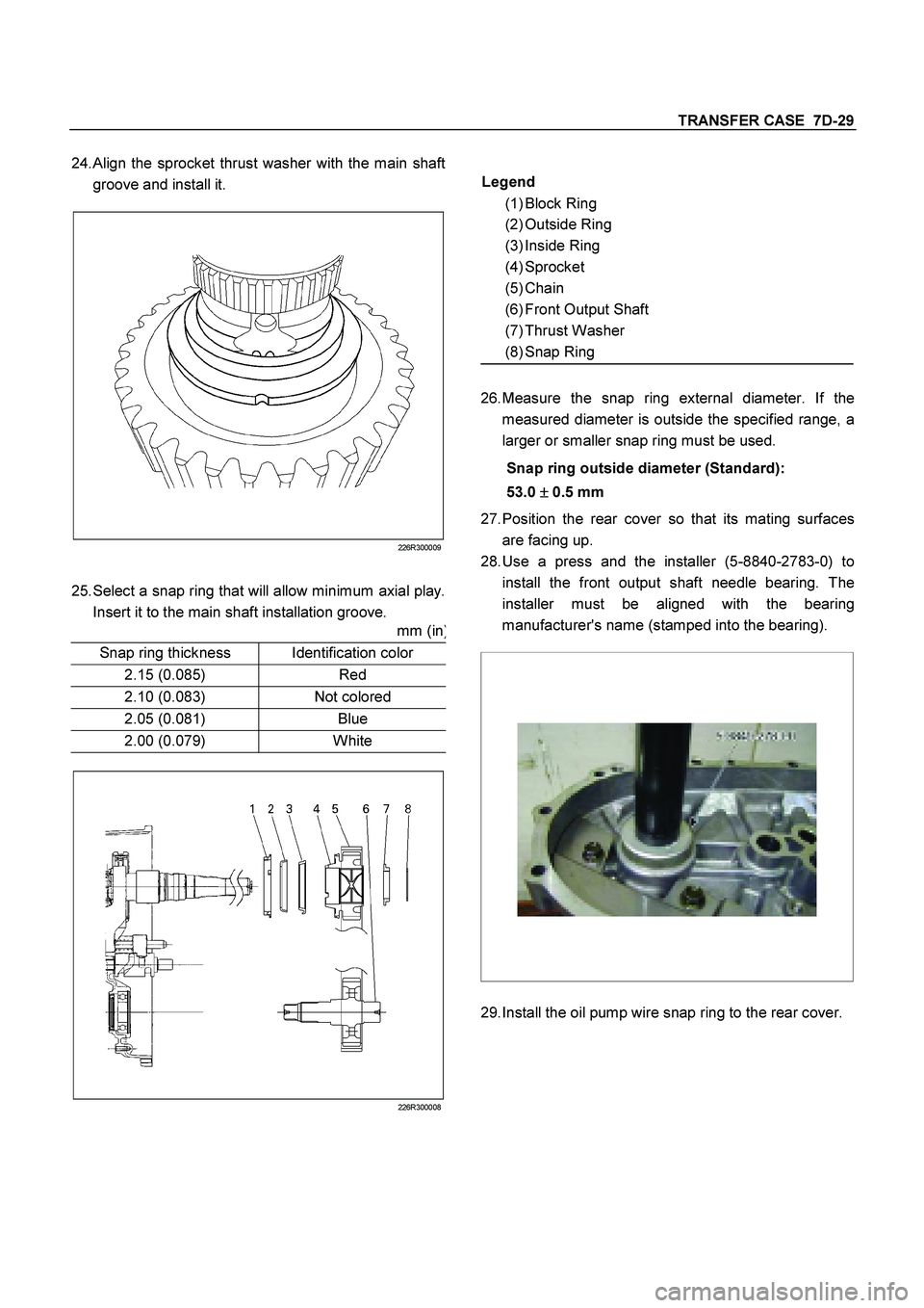
24.
Align the sprocket thrust washer with the main shaft
groove and install it.
226R300009
25. Select a snap ring that will allow minimum axial play.
Insert it to the main shaft installation groove.
mm (in
)
Snap ring thickness
Identification color
2.15 (0.085)
Red
2.10 (0.083)
Not colored
2.05 (0.081)
Blue
2.00 (0.079)
White
226R300008
Legend
(1) Block Ring
(2) Outside Ring
(3) Inside Ring
(4) Sprocket
(5) Chain
(6) Front Output Shaft
(7) Thrust Washer
(8) Snap Ring
26.
Measure the snap ring external diameter. If the
measured diameter is outside the specified range, a
larger or smaller snap ring must be used.
Snap ring outside diameter (Standard):
53.0 �
�� � 0.5 mm
27.
Position the rear cover so that its mating surfaces
are facing up.
28.
Use a press and the installer (5-8840-2783-0) to
install the front output shaft needle bearing. The
installer must be aligned with the bearing
manufacturer's name (stamped into the bearing).
29.
Install the oil pump wire snap ring to the rear cover.
Page 3820 of 4264

7A4–12 UNIT REPAIR (AW30–40LE)
5. Install the second brake drum gasket.
Install a new second brake drum gasket to the
transmission case.
24 0RY 0 001 3
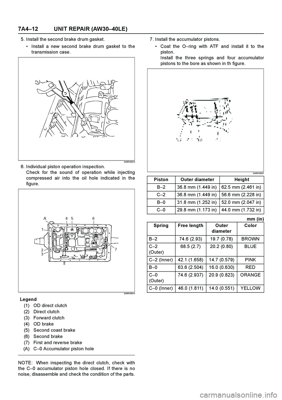
6. Individual piston operation inspection.
Check for the sound of operation while injecting
compressed air into the oil hole indicated in the
figure.
24 0RY 0 001 4
E nd OFCa llou t
NOTE: When inspecting the direct clutch, check with
the C–0 accumulator piston hole closed. If there is no
noise, disassemble and check the condition of the parts.7. Install the accumulator pistons.
Coat the O–ring with ATF and install it to the
piston.
Install the three springs and four accumulator
pistons to the bore as shown in th figure.
24 0RY 0 0027
mm (in)
Legend
(1) OD direct clutch
(2) Direct clutch
(3) Forward clutch
(4) OD brake
(5) Second coast brake
(6) Second brake
(7) First and reverse brake
(A) C–0 Accumulator piston hole
Piston Outer diameter Height
B–2 36.8 mm (1.449 in) 62.5 mm (2.461 in)
C–2 36.8 mm (1.449 in) 56.6 mm (2.228 in)
B–0 31.8 mm (1.252 in) 52.0 mm (2.047 in)
C–0 29.8 mm (1.173 in) 44.0 mm (1.732 in)
Spring Free length Outer
diameterColor
B–2 74.6 (2.93) 19.7 (0.78) BROWN
C–2
(Outer)68.5 (2.7) 20.2 (0.80) BLUE
C–2 (Inner) 42.1 (1.658) 14.7 (0.579) PINK
B–0 63.6 (2.504) 16.0 (0.630) RED
C–0
(Outer)74.6 (2.937) 20.9 (0.823) ORANGE
C–0 (Inner) 46.0 (1.811) 14.0 (0.551) YELLOW
Page 3911 of 4264
UNIT REPAIR (AW30–40LE) 7A4–103
18. Remove the sleeve(31) with the plungers(32)(33),
spring(34) and washer.
Remove the two plungers(32)(33) from the sleeve.
Remove the primary regulator valve(36) from the
valve body(37).
2 44R20 006 0
Inspection and Repair
1. Inspect strainer
Inspect strainer for residual adhesive and damage,
and clean and replace as necessary.
2 44R20 005 1
2. Inspect valve springs
Check for damage, squareness, rust and distorted
coils.
Measure the spring free length and replace if less
than shown below.
mm (in)
2 44R20 0077
SpringFree
lengthColor
(1) By-pass valve21.3
(0.839 )YELLOW
(2) Steel ball20.5
(0.807 )WHITE
(3) 1–2 shift valve 30.8
(1.213 )PURPLE
(4) Low coast modulator valve30.4
(1.197 )LIGHT
GREEN
(5) Accumulator control valve33.8
(1.331)—
(6) Solenoid modulator valve 26.6
(1.047)LIGHT
BLUE
(7) Cut back valve 34.0
(1.339)DARK
BLUE
(8) Primary regulator valve38.58
(1.519)WITHE
Page 4168 of 4264
7A3-16 ON-VEHICLE SERVICE (JR405E)
SOLENOIDS, OIL PRESSURE SWITCH AND OIL TEMPERATURE
SENSOR
244L300003
Legend
1. High clutch oil pressure switch connector
(wire color: Gray)
2. 2-4 brake oil pressure switch connector
(wire color: Brown)
3. Low and reverse brake oil pressure switch connector
(wire color: White)
4. Low and reverse brake duty solenoid connector
(wire color: Pink and White)
5. High clutch duty solenoid connector
(wire color: Green and Gray)
6. Lock-up duty solenoid connector
(wire color: Yellow and Black)
7. 2-4 brake duty solenoid connector
(wire color: Blue and Brown)
8. Low clutch duty solenoid connector
(wire color: Orange and Black)
9. Line pressure solenoid connector
(wire color: Pink)
Page 4189 of 4264
UNIT REPAIR (JR405E) 7A4-15
244L300003
Legend
1. High clutch oil pressure switch connector
(wire color: Gray)
2. 2-4 brake oil pressure switch connector
(wire color: Brown)
3. Low and reverse brake oil pressure
switch connector (wire color: White)
4. Low and reverse brake duty solenoid
connector (wire color: Pink and White)
5. High clutch duty solenoid connector
(wire color: Green and Gray)
6. Lock-up duty solenoid connector (wire
color: Yellow and Black)
7. 2-4 brake duty solenoid connector (wire
color: Blue and Brown)
8. Low clutch duty solenoid connector (wire
color: Orange and Black)
9. Line pressure solenoid connector (wire
color: Pink)