Page 2515 of 4264
ENGINE COOLING 6B-5
Diagnosis
Engine Cooling Trouble
Condition Possible cause Correction
Engine overheating Low Engine Coolant level Replenish
Thermo mater unit faulty Replace
Faulty thermostat Replace
Faulty Engine Coolant temperature
sensor Repair or replace
Clogged radiator Clean or replace
Faulty radiator cap Replace
Low engine oil level or use of
improper engine oil Replenish or change oil
Clogged exhaust system Clean exhaust system or replace
faulty parts
Faulty Throttle Position sensor Replace throttle valve assembly
Open or shorted Throttle Position
sensor circuit Repair or replace
Damaged cylinder head gasket Replace
Loosen V-belt tension Adjust belt tension or replace.
Collapsed hoses Replace
Faulty Fan clutch Replace
Engine overcooling Faulty thermostat Replace
Engine slow to warm-up Faulty thermostat Replace
Thermo unit faulty Replace
Page 2517 of 4264
ENGINE COOLING 6B-7
Water Pump
Water Pump and Associated Parts
Legend
1 Water Pump Assembly 2 O-Ring
3 Bolt
2 3 1
Removal
1. Disconnect battery ground cable.
2. Drain coolant.
3. Disconnect radiator hose (on inlet pipe side).
4. Remove timing belt, refer to "Timing Belt" in this manual.
5. Remove water pump assembly.
Inspection
Make necessary repair and parts replacement if extreme wear
or damage is found during inspection. Should any of the
following problems occur, the entire water pump assembly
must be replaced:
Page 2518 of 4264
6B-8 ENGINE COOLING
� Crack in the water pump body
� EC leakage from the seal unit
� Play or abnormal noise in the bearing
� Cracks or corrosion in the impeller
Installation
1. Before installing water pump, coat sealing surface with
silicon grease.
2. Install water pump assembly and tighten bolts to the
specified torque.
Torque: 25 N�
�� �m (2.5 kgf�
�� �m)
3. Timing belt
� Install timing belt, refer to timing belt installation step in
"Timing Belt" in this manual.
4. Connect radiator hose and replenish EC.
5. Connect battery ground cable.
Page 2562 of 4264
6D3-8 STARTING AND CHARGING SYSTEM
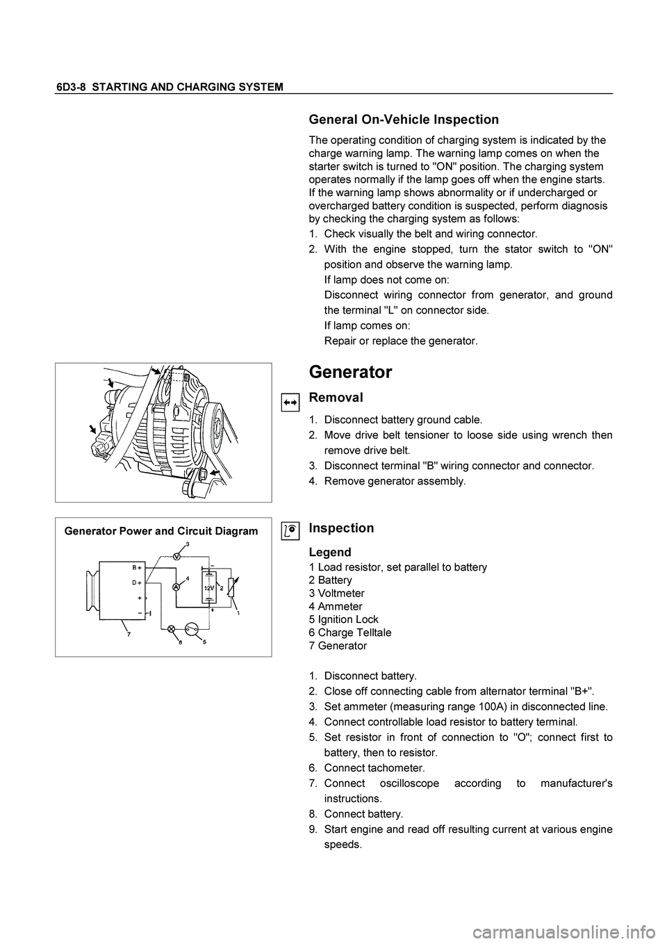
General On-Vehicle Inspection
The operating condition of charging system is indicated by the
charge warning lamp. The warning lamp comes on when the
starter switch is turned to "ON" position. The charging system
operates normally if the lamp goes off when the engine starts.
If the warning lamp shows abnormality or if undercharged or
overcharged battery condition is suspected, perform diagnosis
by checking the charging system as follows:
1. Check visually the belt and wiring connector.
2. With the engine stopped, turn the stator switch to "ON"
position and observe the warning lamp.
If lamp does not come on:
Disconnect wiring connector from generator, and ground
the terminal "L" on connector side.
If lamp comes on:
Repair or replace the generator.
Generator
Removal
1. Disconnect battery ground cable.
2. Move drive belt tensioner to loose side using wrench then
remove drive belt.
3. Disconnect terminal "B" wiring connector and connector.
4. Remove generator assembly.
Generator Power and Circuit Diagram
Inspection
Legend
1 Load resistor, set parallel to battery
2 Battery
3 Voltmeter
4 Ammeter
5 Ignition Lock
6 Charge Telltale
7 Generator
1. Disconnect battery.
2. Close off connecting cable from alternator terminal "B+".
3. Set ammeter (measuring range 100A) in disconnected line.
4. Connect controllable load resistor to battery terminal.
5. Set resistor in front of connection to "O"; connect first to
battery, then to resistor.
6. Connect tachometer.
7. Connect oscilloscope according to manufacturer's
instructions.
8. Connect battery.
9. Start engine and read off resulting current at various engine
speeds.
Page 2563 of 4264
STARTING AND CHARGING SYSTEM 6D3-9
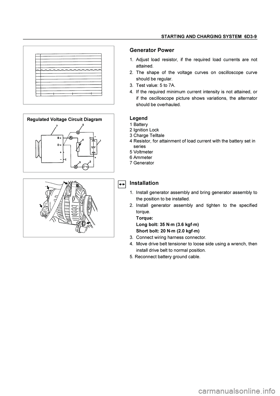
Generator Power
1. Adjust load resistor, if the required load currents are not
attained.
2. The shape of the voltage curves on oscilloscope curve
should be regular.
3. Test value: 5 to 7A.
4. If the required minimum current intensity is not attained, o
r
if the oscilloscope picture shows variations, the alternator
should be overhauled.
Regulated Voltage Circuit Diagram
Legend
1 Battery
2 Ignition Lock
3 Charge Telltale
4 Resistor, for attainment of load current with the battery set in
series
5 Voltmeter
6 Ammeter
7 Generator
Installation
1. Install generator assembly and bring generator assembly to
the position to be installed.
2. Install generator assembly and tighten to the specified
torque.
Torque:
Long bolt: 35 N�
�� �m (3.6 kgf�
�� �m)
Short bolt: 20 N
�
�� �m (2.0 kgf
�
�� �m)
3. Connect wiring harness connector.
4. Move drive belt tensioner to loose side using a wrench, then
install drive belt to normal position.
5. Reconnect battery ground cable.
Page 2573 of 4264
STARTING AND CHARGING SYSTEM 6D3-19
Inspection
Generator
Before any in field testing can be undertaken it is important
that the battery's conditions is established and the terminals
are clean and tight.
Check the condition of the generator drive belt and ensure that
it is adjusted in accordance with the engine manufacturer's
recommnedations.
Battery conditions:
Note: This assessment may be difficult with maintenance free
assemblies.
Test the specific gravity of the individual cells the readings
should be within 10 points of each other, it is recommended
that the average SG should be 1.260 or higher.
A load test should be carried out to determine the ability of the
battery to supply and accept current. This is a good indicator
as to the general condition of the battery.
A load equal to the normal starting current should be placed
across the battery, the duration of this load test should not
exceed 10 seconds, during this time the terminal voltage
across the battery should not drop below 9.6 volts. Observe
each cell for signs of excessive gas liberation, usuall an
indication of cell failure.
If the battery test is clear proceed with the Generator tests as
follows.
Care should be taken when making the following connections.
It is recommended that the battery negative terminal be
disconnected before the test meters are connected, and
reconnecting the negative terminal when the meters are
inserted into the circuit under test. The warning lamp in the D+
circuit should not exceed 2 watts.
Regulating voltage test on the vehicle.
Connect a voltmeter to the generator, the positive lead to the
B+ terminal and the nagative lead to the generator casing.
Select the voltage range to suit the system, i.e. 20v for 12 volt
sysytems or 40v for 24 volt systems. Connect an ammeter in
series with the main output cable from the B+ terminal on the
generator, the range selected must be capable of reading the
maximum output from the generator.
Note the voltmeter reading before starting the engine. This
reading should increase when the engine is running indicating
generator output, start the engine and increase the engine
speed until the generator is running at 4000 rpm, switch on
vehicle loads of 5-10 A is indcated on the ammeter, the
voltmeter shoud read 14.0-14.2 v for a 12 volt system, for a 24
volt system the readings should be 5-10 A and 27.7-28.5 volts.
Page 2811 of 4264
ENGINE DRIVEABILITY AND EMISSIONS 6E–235
22 Perform the procedure in Fuel System Pressure Test
(Refer to 6E-108 �Fuel System Diagnosis�) to
determine if there is a problem with fuel delivery.
Was a problem found?—Verify repair Go to Step 23
23 Refer to 6E-108 page �Fuel System Diagnosis� to
determine if there is a problem with fuel delivery.
Was a problem found?—Verify repair Go to Step 24
24 Check for the following engine mechanical problems
(refer to Engine Mechanical):
Low compression
Leaking cylinder head gaskets
Worn camshaft
Camshaft drive belt slipped or stripped
Was a problem found?—Verify repair Go to Step 25
25 1. Review all diagnostic procedures within this table.
2. If all procedures have been completed and no
malfunctions have been found, review/inspect the
followi ng:
Visual/physical inspection
Te c h 2 d a t a
All electrical connections within a suspected
circuit and/or system
Was a problem found?—Verify repair Go to Step 26
26 Is the ECM programmed with the latest software
release?
If not, download the latest software to the ECM using
the “SPS (Service Programming System)”.
Was the problem solved?—Verify repair Go to Step 27
27 Replace the ECM.
Is the action complete?
IMPORTANT: The replacement ECM must be
programmed. Refer to section of the Service
Programming System (SPS) in this manual.
Following ECM programming, the immobilizer system
(if equipped) must be linked to the ECM. Refer to
section 11 “Immobilizer System-ECM replacement” for
the ECM/Immobilizer linking procedure.—Verify Repair— Step Action Value(s) Yes No
Page 2814 of 4264
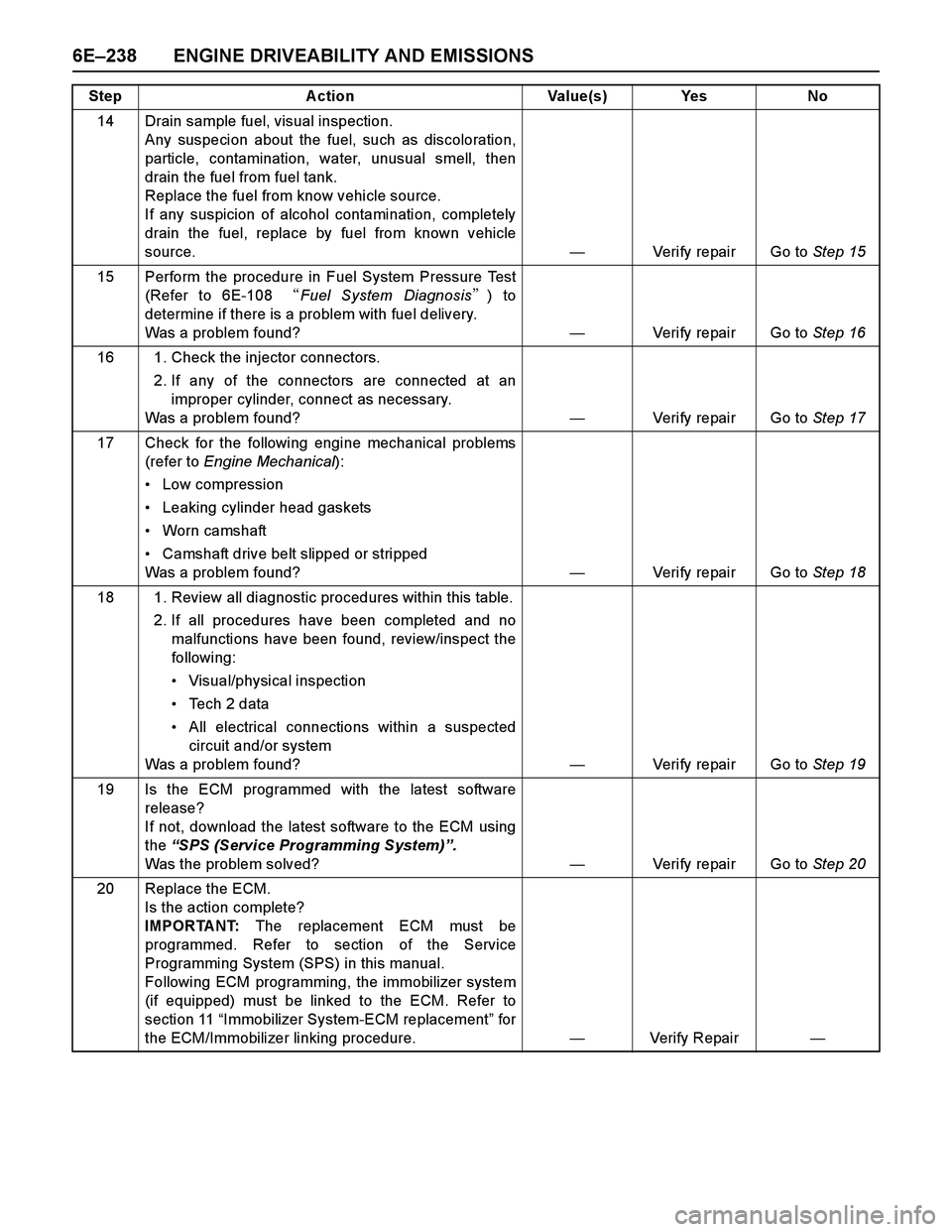
6E–238 ENGINE DRIVEABILITY AND EMISSIONS
14 Drain sample fuel, visual inspection.
Any suspecion about the fuel, such as discoloration,
particle, contamination, water, unusual smell, then
drain the fuel from fuel tank.
Replace the fuel from know vehicle source.
If any suspicion of alcohol contamination, completely
drain the fuel, replace by fuel from known vehicle
source.—Verify repair Go to Step 15
15 Perform the procedure in Fuel System Pressure Test
(Refer to 6E-108 �Fuel System Diagnosis�) to
determine if there is a problem with fuel delivery.
Was a problem found?—Verify repair Go to Step 16
16 1. Check the injector connectors.
2. If any of the connectors are connected at an
improper cylinder, connect as necessary.
Was a problem found?—Verify repair Go to Step 17
17 Check for the following engine mechanical problems
(refer to Engine Mechanical):
Low compression
Leaking cylinder head gaskets
Worn camshaft
Camshaft drive belt slipped or stripped
Was a problem found?—Verify repair Go to Step 18
18 1. Review all diagnostic procedures within this table.
2. If all procedures have been completed and no
malfunctions have been found, review/inspect the
followi ng:
Visual/physical inspection
Te c h 2 d a t a
All electrical connections within a suspected
circuit and/or system
Was a problem found?—Verify repair Go to Step 19
19 Is the ECM programmed with the latest software
release?
If not, download the latest software to the ECM using
the “SPS (Service Programming System)”.
Was the problem solved?—Verify repair Go to Step 20
20 Replace the ECM.
Is the action complete?
IMPORTANT: The replacement ECM must be
programmed. Refer to section of the Service
Programming System (SPS) in this manual.
Following ECM programming, the immobilizer system
(if equipped) must be linked to the ECM. Refer to
section 11 “Immobilizer System-ECM replacement” for
the ECM/Immobilizer linking procedure.—Verify Repair— Step Action Value(s) Yes No