Page 3050 of 4264
1-40 HEATER AND AIR CONDITIONING
COMPRESSOR
REMOVAL AND INSTALLATION (4J ENGINE)
852R300006
Removal Steps
1. Air duct
2. Magnetic clutch harness connector
3. Lock nut
4. Tension adjustment bolt
5. Drive belt
6. Refrigerant line
7. Bolt; compressor to bracket
8. Compressor assembly
Installation Steps
8. Compressor assembly
� 7. Bolt; compressor to bracket
� 6. Refrigerant line
5. Drive belt
4. Tension adjustment bolt
3. Lock nut
2. Magnetic clutch harness connector
1. Air duct
Page 3051 of 4264
HEATER AND AIR CONDITIONING 1-41
Important Operations - Installation
7. Bolt; Compressor to Bracket
N�m (kgf�m/lb�ft)
Torque 44 (4.5/33)
6. Refrigerant Line
N�m (kgf�m/lb�ft)
Torque 11�19 (1.1/9.5�1.9/14)
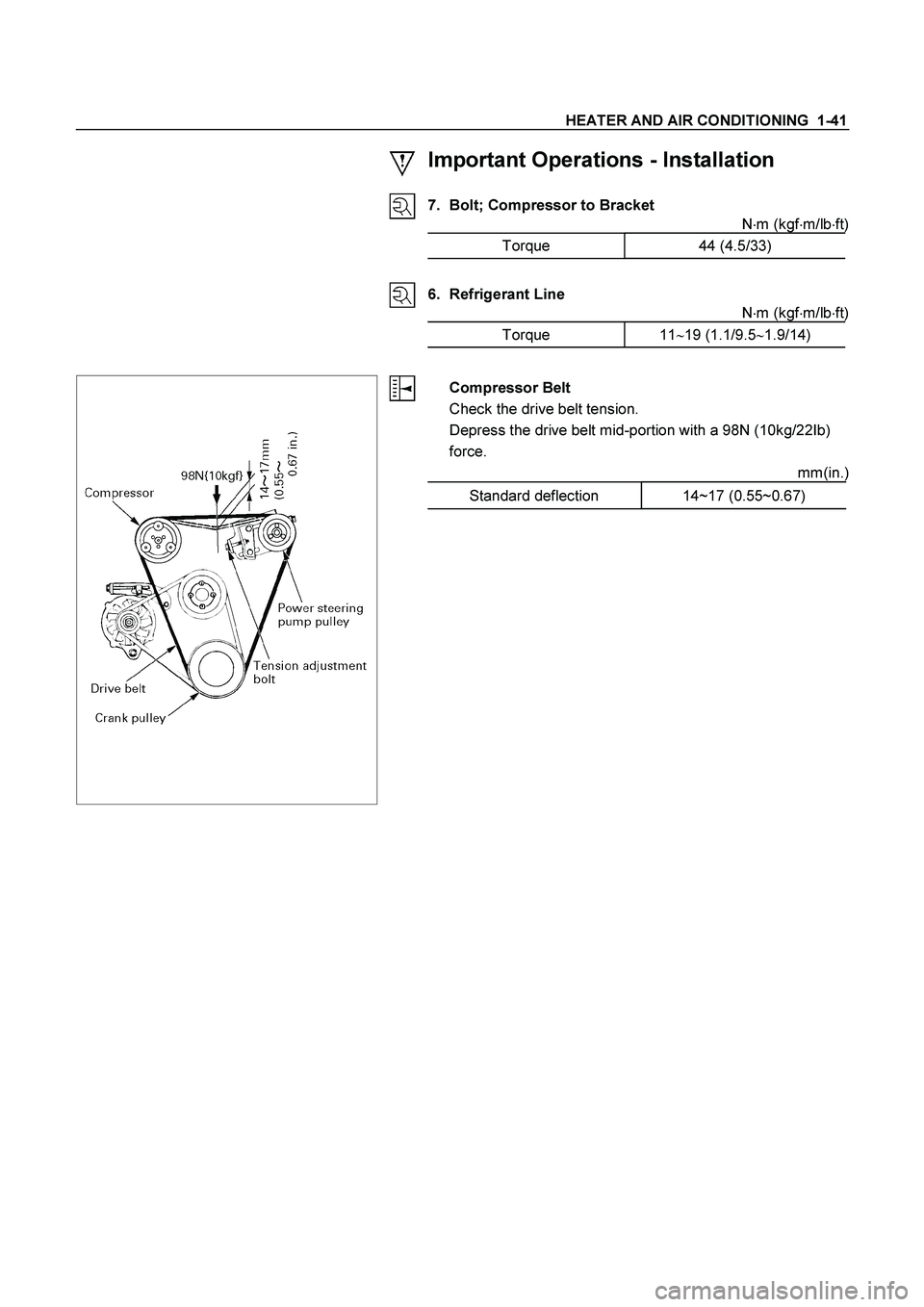
Compressor Belt
Check the drive belt tension.
Depress the drive belt mid-portion with a 98N (10kg/22Ib)
force.
mm(in.)
Standard deflection 14~17 (0.55~0.67)
Page 3052 of 4264
1-42 HEATER AND AIR CONDITIONING
REMOVAL AND INSTALLATION (6VE1)
RTW310MF000301
Removal Steps
1. Magnetic clutch harness connector
2. Compressor belt
3. Refrigerant line
4. Bolt; compressor to bracket
5. Compressor assembly
Installation Steps
5. Compressor assembly
� 4. Bolt; compressor to bracket
� 3. Refrigerant line
� 2. Compressor belt
1. Magnetic clutch harness connector
Page 3053 of 4264
HEATER AND AIR CONDITIONING 1-43
Important Operations - Installation
4. Bolt; Compressor to Bracket
N�m (kgf�m/lb�ft)
Torque 19 (1.9/14)
3. Refrigerant Line
N�m (kgf�m/lb�ft)
Torque 11�19 (1.1/9.5�1.9/14)
RTW310MH000101
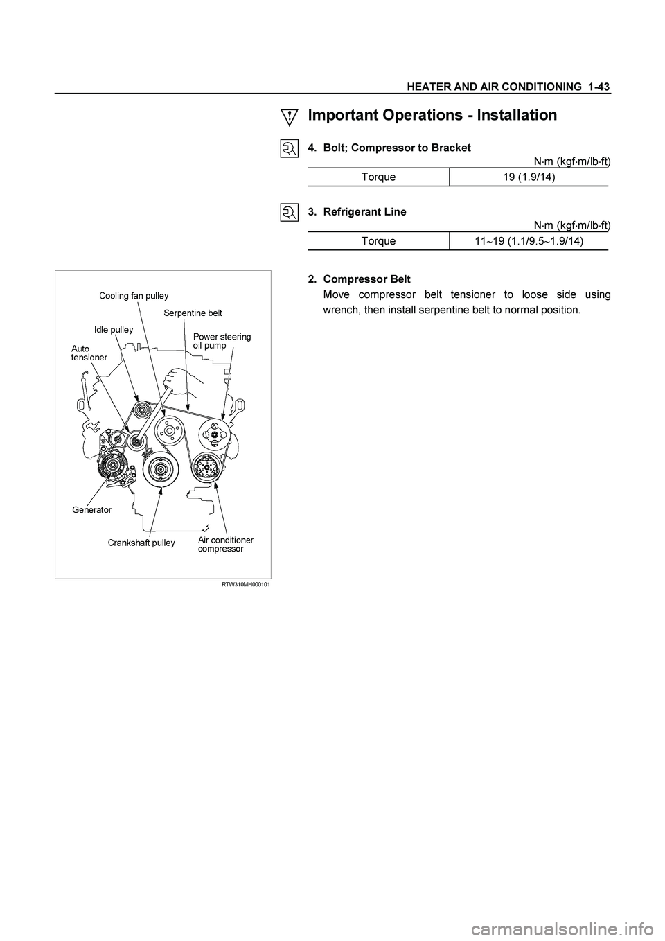
2. Compressor Belt
Move compressor belt tensioner to loose side using
wrench, then install serpentine belt to normal position.
Page 3054 of 4264
1-44 HEATER AND AIR CONDITIONING
REMOVAL AND INSTALLATION (C24SE)
RTW310MF000401
Removal Steps
1. Magnetic clutch harness connector
2. Compressor belt
3. Refrigerant line
4. Bolt; compressor to bracket
5. Compressor assembly
Installation Steps
5. Compressor assembly
� 4. Bolt; compressor to bracket
� 3. Refrigerant line
� 2. Compressor belt
1. Magnetic clutch harness connector
Page 3055 of 4264
HEATER AND AIR CONDITIONING 1-45
Important Operations - Installation
4. Bolt; Compressor to Bracket
N�m (kgf�m/lb�ft)
Torque 19 (1.9/14)
3. Refrigerant Line
N�m (kgf�m/lb�ft)
Torque 11�19 (1.1/9.5�1.9/14)
2. Compressor Belt
Move compressor belt tensioner to loose side using
wrench, then install serpentine belt to normal position.
Page 3093 of 4264

HEATER AND AIR CONDITIONING 1-83
AIR CONDITIONING CYCLE TROUBLESHOOTING
TROUBLE POSSIBLE CAUSE CORRECTION
No cooling or
insufficient
cooling
1. Magnetic clutch does not run
��
Refer to “MAGNETIC CLUTCH”
troubleshooting in this section
2. Compressor is not rotating properly
��Drive belt loosened or broken ��
Adjust the drive belt to the specified
tension or replace the drive belt
��Magnetic clutch face is not clean and
slips ��Clean the magnetic clutch face or replace
��
Incorrect clearance between magnetic
drive plate and pulley ��
Adjust the clearance (Refer to
“COMPRESSOR OVERHAUL”
��
Compressor oil leaks from shaft seal or
shell ��
Replace the compressor
��
Compressor seized ��
Replace the compressor
3. Insufficient or excessive charge of
refrigerant ��
Discharge and recover refrigerant.
Recharge to specified amount.
4. Leaks in the refrigerant system
��
Check refrigerant system for leaks and
repair as necessary
Discharge and recover refrigerant.
Recharge to specified amount.
5. Condenser clogged or insufficient radiation
��Clean the condenser or replace as
necessary
��
Check radiator or condenser fan function
6. Temperature control link unit of the heater
unit defective ��
Repair the link unit
7. Unsteady operation due to foreign
substance in expansion valve ��
Replace the expansion valve
8. Poor operation of electronic thermostat
��
Check electronic thermostat and replace
as necessary
Insufficient
velocity
of cooling air
1. Evaporator clogged or frosted
��
Check evaporator core and replace or
clean the core
2. Air leaking from cooling unit or air duct
��Check evaporator and duct connection,
then repair as necessary
3. Blower motor does not rotate prop-erly
��
Refer to “FAN CONTROL KNOB (FAN
SWITCH)” troubleshooting in this section
* For the execution of the charging and discharging operation in the table above, refer to the “RECOVERY,
RECYCLING, EVACUATING AND CHARGING” in this section.
Page 3437 of 4264
 Bolt
(2) Hose
(3) Power Steering Unit
(4) Power Steering Pump
Test of fluid press")
POWER-ASSISTED STEERING SYSTEM 3B-7
Power Steering System Test
Test Procedure
F02RX002
Legend
(1) Bolt
(2) Hose
(3) Power Steering Unit
(4) Power Steering Pump
Test of fluid pressure in the power steering system is
performed to determine whether or not the oil pump and
power steering unit are functioning normally.
The power steering system test is used to identify and
isolate hydraulic circuit difficulties. Prior to performing
this test, the following inspections and corrections, i
f
necessary, must be made.
��
Inspect pump reservoir for proper fluid level.
��
Inspect pump belt for proper tension.
��
Inspect pump driver pulley condition.
1. Place a container under the pump to catch the fluid
when disconnecting or connecting the hoses.
2.
With the engine NOT running, disconnect the
pressure hose at the power steering pump and
install power steering tester 5-8840-0135-0 as
shown in the illustration. The gage must be between
the shutoff valve and pump. Open the shutoff valve.
3. Check the fluid level. Fill the reservoir with powe
r
steering fluid, to the "Full" mark. Start the engine,
then turn the steering wheel and momentarily hold it
against a stop (right or left). Turn the engine off and
check the connections at tester for leakage.
4. Bleed the system. Refer to Bleeding the Powe
r
Steering System in this section.
5. Start the engine and check the fluid level. Add
power steering fluid if required. When the engine is
at normal operating temperature, increase engine
speed to 1500 rpm.
CAUTION: Do not leave shutoff valve fully closed
for more than 5 seconds, as the pump could
become damaged internally.

852R300006
Removal Steps
1. Air duct
2. Magnetic clutch harness connector
3. Lock nut")

RTW310MF000301
Removal Steps
1. Magnetic clutch harness connector
2. Compressor belt
3. Refrigerant line")

RTW310MF000401
Removal Steps
1. Magnetic clutch harness connector
2. Compressor belt
3. Refrigerant line")