Page 1677 of 4264
4JA1/4JH1 ENGINE DRIVEABILITY AND EMISSIONS 6E–305
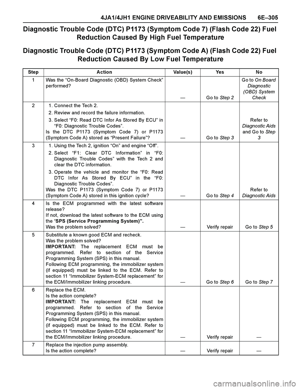
Diagnostic Trouble Code (DTC) P1173 (Symptom Code 7) (Flash Code 22) Fuel
Reduction Caused By High Fuel Temperature
Diagnostic Trouble Code (DTC) P1173 (Sy mptom Code A) (Flash Code 22) Fuel
Reduction Caused By Low Fuel Temperature
Step Action Value(s) Yes No
1Was the “On-Board Diagnostic (OBD) System Check”
performed?
—Go to Step 2Go to On Board
Diagnostic
(OBD) System
Check
2 1. Connect the Tech 2.
2. Review and record the failure information.
3. Select “F0: Read DTC Infor As Stored By ECU” in
“F0: Diagnostic Trouble Codes”.
Is the DTC P1173 (Symptom Code 7) or P1173
(Symptom Code A) stored as “Present Failure”?—Go to Step 3Refer to
Diagnostic Aids
and Go to Step
3
3 1. Using the Tech 2, ignition “On” and engine “Off”.
2. Select “F1: Clear DTC Information” in “F0:
Diagnostic Trouble Codes” with the Tech 2 and
clear the DTC information.
3. Operate the vehicle and monitor the “F0: Read
DTC Infor As Stored By ECU” in the “F0:
Diagnostic Trouble Codes”.
Was the DTC P1173 (Symptom Code 7) or P1173
(Symptom Code A) stored in this ignition cycle?—Go to Step 4Refer to
Diagnostic Aids
4 Is the ECM programmed with the latest software
release?
If not, download the latest software to the ECM using
the “SPS (Service Programming System)”.
Was the problem solved?—Verify repair Go to Step 5
5 Substitute a known good ECM and recheck.
Was the problem solved?
IMPORTANT: The replacement ECM must be
programmed. Refer to section of the Service
Programming System (SPS) in this manual.
Following ECM programming, the immobilizer system
(if equipped) must be linked to the ECM. Refer to
section 11 “Immobilizer System-ECM replacement” for
the ECM/Immobilizer linking procedure. —Go to Step 6Go to Step 7
6 Replace the ECM.
Is the action complete?
IMPORTANT: The replacement ECM must be
programmed. Refer to section of the Service
Programming System (SPS) in this manual.
Following ECM programming, the immobilizer system
(if equipped) must be linked to the ECM. Refer to
section 11 “Immobilizer System-ECM replacement” for
the ECM/Immobilizer linking procedure.—Verify repair—
7 Replace the injection pump assembly.
Is the action complete?—Verify repair—
Page 1678 of 4264
6E–306 4JA1/4JH1 ENGINE DRIVEABILITY AND EMISSIONS
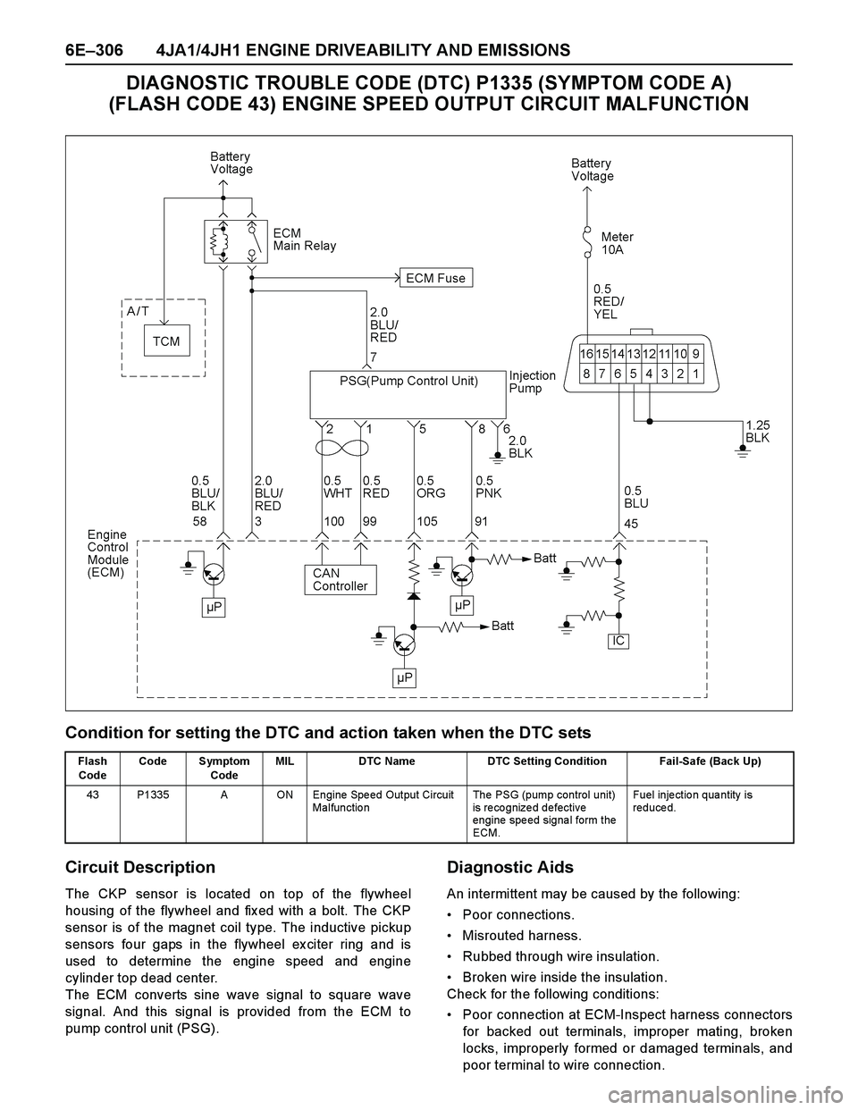
DIAGNOSTIC TROUBLE CODE (DTC) P1335 (SYMPTOM CODE A)
(FLASH CODE 43) ENGINE SPEED OUTPUT CIRCUIT MALFUNCTION
Condition for setting the DTC and action taken when the DTC sets
Circuit Description
The CKP sensor is located on top of the flywheel
housing of the flywheel and fix ed with a bolt. The CKP
sensor is of the magnet coil type. The inductive pickup
sensors four gaps in the flywheel ex citer ring and is
used to determine the engine speed and engine
cylinder top dead center.
The ECM converts sine wave signal to square wave
signal. And this signal is provided from the ECM to
pump control unit (PSG).
Diagnostic Aids
An intermittent may be caused by the following:
Poor connections.
Misrouted harness.
Rubbed through wire insulation.
Broken wire inside the insulation.
Check for the following conditions:
Poor connection at ECM-Inspect harness connectors
for backed out terminals, improper mating, broken
locks, improperly formed or damaged terminals, and
poor terminal to wire connection.
Flash
CodeCode Symptom
CodeMIL DTC Name DTC Setting Condition Fail-Safe (Back Up)
43 P1335 A ON Engine Speed Output Circuit
Malfunctio nThe PSG (pump control unit)
is recognized defective
engine speed signal form the
ECM.Fuel inje ctio n qua ntity is
reduced.
Page 1712 of 4264
6E–340 4JA1/4JH1 ENGINE DRIVEABILITY AND EMISSIONS
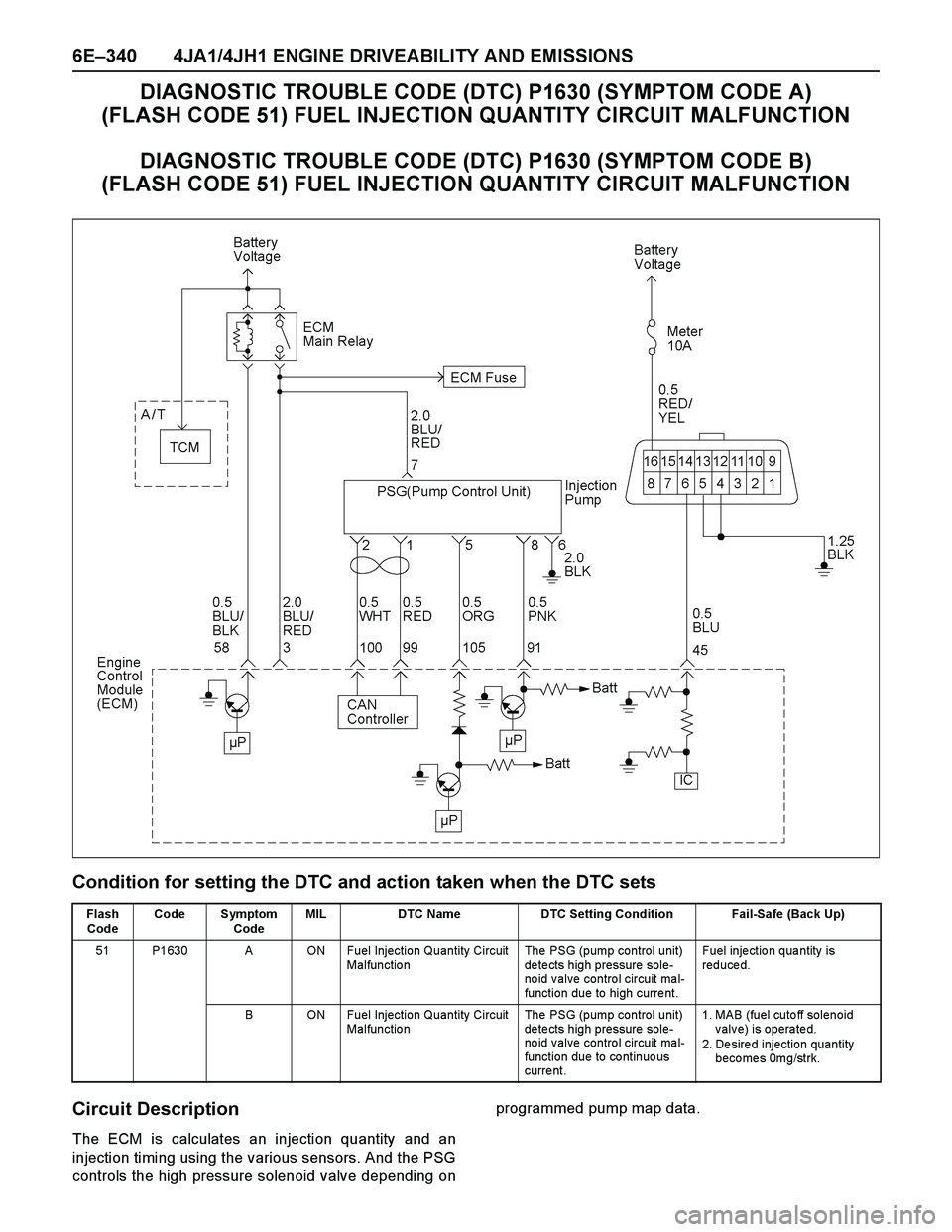
DIAGNOSTIC TROUBLE CODE (DTC) P1630 (SYMPTOM CODE A)
(FLASH CODE 51) FUEL INJECTION QUANTITY CIRCUIT MALFUNCTION
DIAGNOSTIC TROUBLE CODE (DTC) P1630 (SYMPTOM CODE B)
(FLASH CODE 51) FUEL INJECTION QUANTITY CIRCUIT MALFUNCTION
Condition for setting the DTC and action taken when the DTC sets
Circuit Description
The ECM is calculates an injection quantity and an
injection timing using the various sensors. And the PSG
controls the high pressure solenoid valve depending onprogrammed pump map data.
Flash
CodeCode Symptom
CodeMIL DTC Name DTC Setting Condition Fail-Safe (Back Up)
51 P1630 A ON Fuel Injection Quantity Circuit
Malfunctio nThe PSG (pump control unit)
de te cts high pressure sole-
no id v alve contro l circuit ma l-
function due to high curre nt.Fuel inje ctio n qua ntity is
reduced.
B ON Fuel Injection Quantity Circuit
Malfunctio nThe PSG (pump control unit)
de te cts high pressure sole-
no id v alve contro l circuit ma l-
function due to co ntinuo us
curre nt.1. MAB (fuel cutoff solenoid
valve) is operated.
2. Desired injection quantity
becomes 0mg/strk.
Page 1713 of 4264
4JA1/4JH1 ENGINE DRIVEABILITY AND EMISSIONS 6E–341
Diagnostic Aids
An intermittent may be caused by the following:
Poor connections.
Misrouted harness.
Rubbed through wire insulation.Broken wire inside the insulation.
Check for the following conditions:
Poor connection at ECM and PSG-Inspect harness
connectors for backed out terminals, improper
mating, broken locks, improperly formed or damaged
terminals, and poor terminal to wire connection.
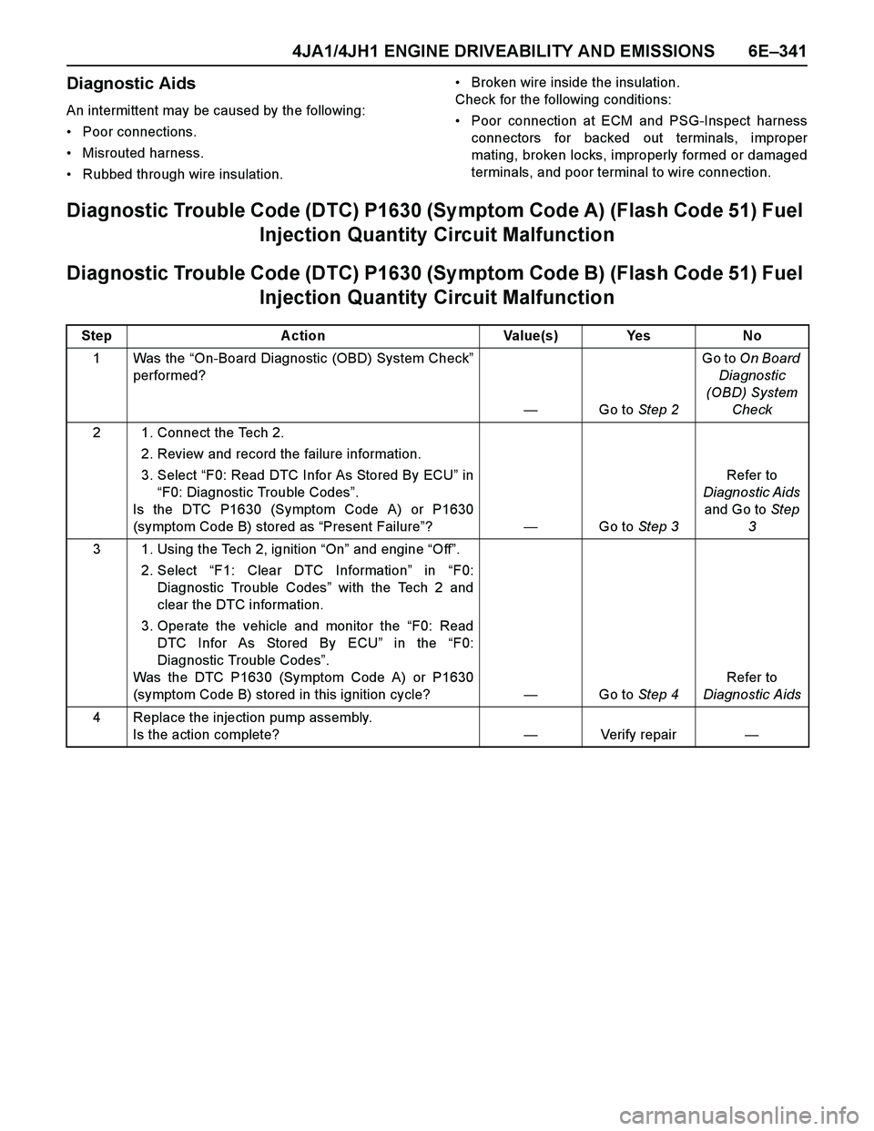
Diagnostic Trouble Code (DTC) P1630 (Sy mptom Code A) (Flash Code 51) Fuel
Injection Quantity Circuit Malfunction
Diagnostic Trouble Code (DTC) P1630 (Sy mptom Code B) (Flash Code 51) Fuel
Injection Quantity Circuit Malfunction
Step Action Value(s) Yes No
1Was the “On-Board Diagnostic (OBD) System Check”
performed?
—Go to Step 2Go to On Board
Diagnostic
(OBD) System
Check
2 1. Connect the Tech 2.
2. Review and record the failure information.
3. Select “F0: Read DTC Infor As Stored By ECU” in
“F0: Diagnostic Trouble Codes”.
Is the DTC P1630 (Symptom Code A) or P1630
(symptom Code B) stored as “Present Failure”?—Go to Step 3Refer to
Diagnostic Aids
and Go to Step
3
3 1. Using the Tech 2, ignition “On” and engine “Off”.
2. Select “F1: Clear DTC Information” in “F0:
Diagnostic Trouble Codes” with the Tech 2 and
clear the DTC information.
3. Operate the vehicle and monitor the “F0: Read
DTC Infor As Stored By ECU” in the “F0:
Diagnostic Trouble Codes”.
Was the DTC P1630 (Symptom Code A) or P1630
(symptom Code B) stored in this ignition cycle?—Go to Step 4Refer to
Diagnostic Aids
4 Replace the injection pump assembly.
Is the action complete?—Verify repair—
Page 1721 of 4264
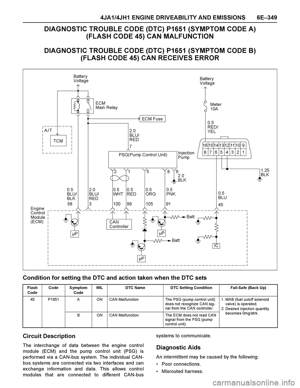
4JA1/4JH1 ENGINE DRIVEABILITY AND EMISSIONS 6E–349
DIAGNOSTIC TROUBLE CODE (DTC) P1651 (SYMPTOM CODE A)
(FLASH CODE 45) CAN MALFUNCTION
DIAGNOSTIC TROUBLE CODE (DTC) P1651 (SYMPTOM CODE B)
(FLASH CODE 45) CAN RECEIVES ERROR
Condition for setting the DTC and action taken when the DTC sets
Circuit Description
The interchange of data between the engine control
module (ECM) and the pump control unit (PSG) is
performed via a CAN-bus system. The individual CAN-
bus systems are connected via two interfaces and can
ex change information and data. This allows control
modules that are connected to different CAN-bussystems to communicate. Diagnostic Aids
An intermittent may be caused by the following:
Poor connections.
Misrouted harness.
Flash
CodeCode Symptom
CodeMIL DTC Name DTC Setting Condition Fail-Safe (Back Up)
45 P1651 A ON CAN Ma lfunction The PSG (pump control unit)
do es not re co gnize CAN sig-
na l from the CAN co ntrolle r.1. MAB (fuel cutoff solenoid
valve) is operated.
2. Desired injection quantity
becomes 0mg/strk.
B ON CAN Ma lfunction The ECM do es not re ad CAN
signal from the PSG (pump
control unit).
Page 1736 of 4264
6E–364 4JA1/4JH1 ENGINE DRIVEABILITY AND EMISSIONS
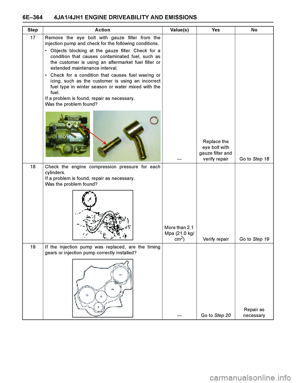
17 Remove the eye bolt with gauze filter from the
injection pump and check for the following conditions.
Objects blocking at the gauze filter. Check for a
condition that causes contaminated fuel, such as
the customer is using an aftermarket fuel filter or
ex tended maintenance interval.
Check for a condition that causes fuel wax ing or
icing, such as the customer is using an incorrect
fuel type in winter season or water mix ed with the
fuel.
If a problem is found, repair as necessary.
Was the problem found?
—Replace the
eye bolt with
gauze filter and
verify repair Go to Step 18
18 Check the engine compression pressure for each
cylinders.
If a problem is found, repair as necessary.
Was the problem found?
More than 2.1
Mpa (21.0 kg/
cm
2) Verify repair Go to Step 19
19 If the injection pump was replaced, are the timing
gears or injection pump correctly installed?
—Go to Step 20Repair as
necessary Step Action Value(s) Yes No
Page 1740 of 4264
6E–368 4JA1/4JH1 ENGINE DRIVEABILITY AND EMISSIONS
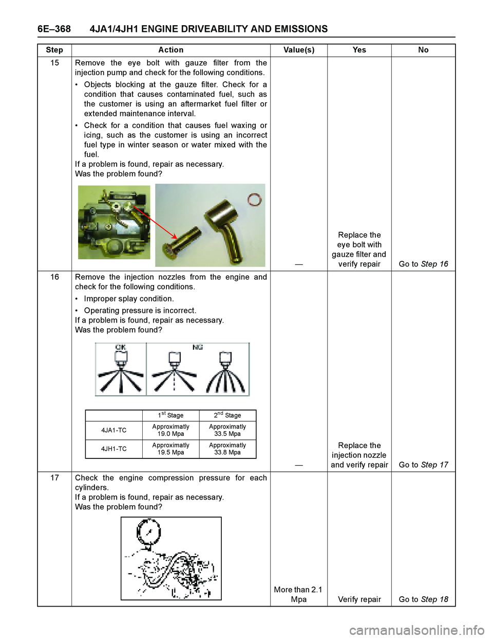
15 Remove the eye bolt with gauze filter from the
injection pump and check for the following conditions.
Objects blocking at the gauze filter. Check for a
condition that causes contaminated fuel, such as
the customer is using an aftermarket fuel filter or
ex tended maintenance interval.
Check for a condition that causes fuel wax ing or
icing, such as the customer is using an incorrect
fuel type in winter season or water mix ed with the
fuel.
If a problem is found, repair as necessary.
Was the problem found?
—Replace the
eye bolt with
gauze filter and
verify repair Go to Step 16
16 Remove the injection nozzles from the engine and
check for the following conditions.
Improper splay condition.
Operating pressure is incorrect.
If a problem is found, repair as necessary.
Was the problem found?
—Replace the
injection nozzle
and verify repair Go to Step 17
17 Check the engine compression pressure for each
cylinders.
If a problem is found, repair as necessary.
Was the problem found?
More than 2.1
Mpa Verify repair Go to Step 18 Step Action Value(s) Yes No
1st Stage 2nd Sta ge
4JA1-TCApproximatly
19.0 MpaApprox ima tly
33.5 Mpa
4JH1-TCApproximatly
19.5 MpaApprox ima tly
33.8 Mpa
Page 1746 of 4264
6E–374 4JA1/4JH1 ENGINE DRIVEABILITY AND EMISSIONS
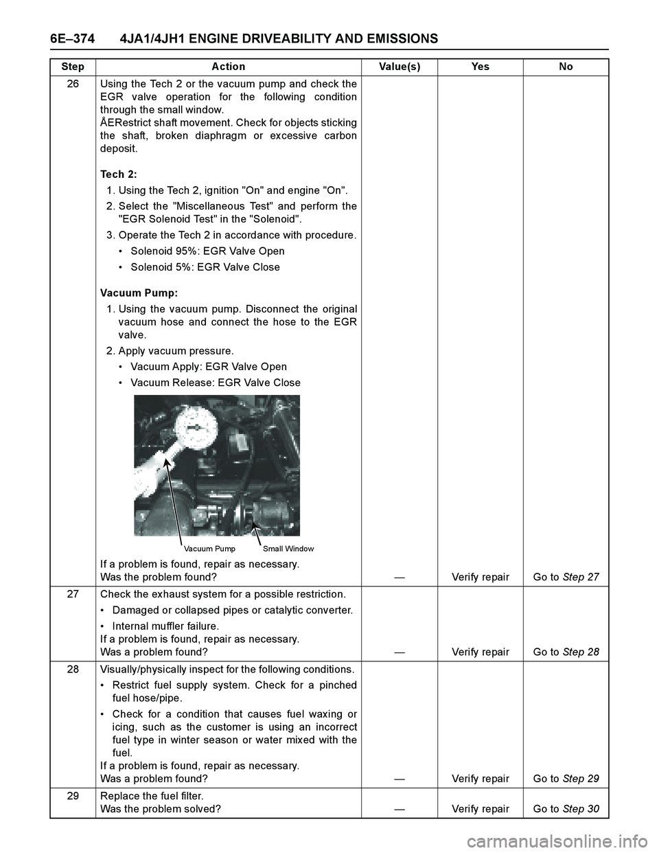
26 Using the Tech 2 or the vacuum pump and check the
EGR valve operation for the following condition
through the small window.
ÅERestrict shaft movement. Check for objects sticking
the shaft, broken diaphragm or ex cessive carbon
deposit.
Tech 2:
1. Using the Tech 2, ignition "On" and engine "On".
2. Select the "Miscellaneous Test" and perform the
"EGR Solenoid Test" in the "Solenoid".
3. Operate the Tech 2 in accordance with procedure.
Solenoid 95%: EGR Valve Open
Solenoid 5%: EGR Valve Close
Vacuum Pump:
1. Using the vacuum pump. Disconnect the original
vacuum hose and connect the hose to the EGR
valve.
2. Apply vacuum pressure.
Vacuum Apply: EGR Valve Open
Vacuum Release: EGR Valve Close
If a problem is found, repair as necessary.
Was the problem found?—Verify repair Go to Step 27
27 Check the ex haust system for a possible restriction.
Damaged or collapsed pipes or catalytic converter.
Internal muffler failure.
If a problem is found, repair as necessary.
Was a problem found?—Verify repair Go to Step 28
28 Visually/physically inspect for the following conditions.
Restrict fuel supply system. Check for a pinched
fuel hose/pipe.
Check for a condition that causes fuel wax ing or
icing, such as the customer is using an incorrect
fuel type in winter season or water mix ed with the
fuel.
If a problem is found, repair as necessary.
Was a problem found?—Verify repair Go to Step 29
29 Replace the fuel filter.
Was the problem solved?—Verify repair Go to Step 30 Step Action Value(s) Yes No
Vacuum Pump Small Window