SRS-58
DIAGNOSIS SENSOR UNIT
Revision: August 20072004 QX56
DIAGNOSIS SENSOR UNITPFP:28556
Removal and InstallationEHS0 00 W T
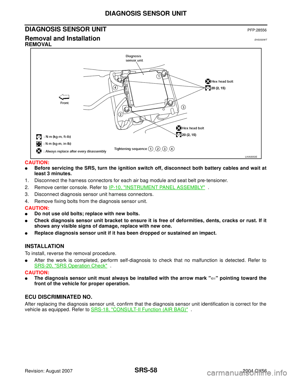
REMOVAL
CAUTION:
�Before servicing the SRS, turn the ignition switch off, disconnect both battery cables and wait at
least 3 minutes.
1. Disconnect the harness connectors for each air bag module and seat belt pre-tensioner.
2. Remove center console. Refer to IP-10, "
INSTRUMENT PANEL ASSEMBLY" .
3. Disconnect diagnosis sensor unit harness connectors.
4. Remove fixing bolts from the diagnosis sensor unit.
CAUTION:
�Do not use old bolts; replace with new bolts.
�Check diagnosis sensor unit bracket to ensure it is free of deformities, dents, cracks or rust. If it
shows any visible signs of damage, replace with new one.
�Replace diagnosis sensor unit if it has been dropped or sustained an impact.
INSTALLATION
To install, reverse the removal procedure.
�After the work is completed, perform self-diagnosis to check that no malfunction is detected. Refer to
SRS-20, "
SRS Operation Check" .
CAUTION:
�The diagnosis sensor unit must always be installed with the arrow mark "⇐" pointing toward the
front of the vehicle for proper operation.
ECU DISCRIMINATED NO.
After replacing the diagnosis sensor unit, confirm that the diagnosis sensor unit identification is correct for the
vehicle as equipped. Refer to SRS-18, "
CONSULT-II Function (AIR BAG)" .
LHIA0053E
PRECAUTIONS
TF-9
C
E
F
G
H
I
J
K
L
MA
B
TF
Revision: August 20072004 QX56
Service NoticeEDS0017L
1. Before proceeding with disassembly, thoroughly clean the outside of the all-mode 4WD transfer. It is
important to prevent the internal parts from becoming contaminated by dirt or other foreign matter.
2. Disassembly should be done in a clean work area.
3. Use lint-free cloth or towels for wiping parts clean. Common shop rags can leave fibers that could interfere
with the operation of the all-mode 4WD transfer.
4. Place disassembled parts in order for easier and proper assembly.
5. All parts should be carefully cleaned with a general purpose, non-flammable solvent before inspection or
reassembly.
6. Gaskets, seals and O-rings should be replaced any time the all-mode 4WD transfer is disassembled.
7. It is very important to perform functional tests whenever they are indicated.
8. The valve body contains precision parts and requires extreme care when parts are removed and serviced.
Place removed parts in a parts rack in order to replace them in correct positions and sequences. Care will
also prevent springs and small parts from becoming scattered or lost.
9. Properly installed valves, sleeves, plugs, etc. will slide along bores in valve body under their own weight.
10. Before assembly, apply a coat of recommended ATF to all parts. Apply petroleum jelly to protect O-rings
and seals, and to hold bearings and washers in place during assembly. Do not use grease.
11. Extreme care should be taken to avoid damage to O-rings, seals and gaskets when assembling.
12. After overhaul, refill the transfer with new ATF.
13. When the all-mode 4WD transfer drain plug is removed, only some of the fluid is drained. Old all-mode
4WD transfer fluid will remain in torque converter and ATF cooling system. Always follow the proper pro-
cedure. Refer to MA-24, "
Changing Transfer Fluid" .
Wiring Diagrams and Trouble DiagnosisEDS001CE
When you read wiring diagrams, refer to the following:
� GI-15, "How to Read Wiring Diagrams" .
� PG-4, "POWER SUPPLY ROUTING CIRCUIT" for power distribution circuit.
When you perform trouble diagnosis, refer to the following:
�GI-11, "HOW TO FOLLOW TEST GROUPS IN TROUBLE DIAGNOSES".
�GI-27, "How to Perform Efficient Diagnosis for an Electrical Incident".