Page 2161 of 3371
GW-26
POWER WINDOW SYSTEM
Revision: August 20072004 QX56
WIWA1098E
Page 2162 of 3371
POWER WINDOW SYSTEM
GW-27
C
D
E
F
G
H
J
K
L
MA
B
GW
Revision: August 20072004 QX56
WIWA1099E
Page 2163 of 3371
GW-28
POWER WINDOW SYSTEM
Revision: August 20072004 QX56
WIWA0217E
Page 2164 of 3371
POWER WINDOW SYSTEM
GW-29
C
D
E
F
G
H
J
K
L
MA
B
GW
Revision: August 20072004 QX56
WIWA0218E
Page 2165 of 3371

GW-30
POWER WINDOW SYSTEM
Revision: August 20072004 QX56
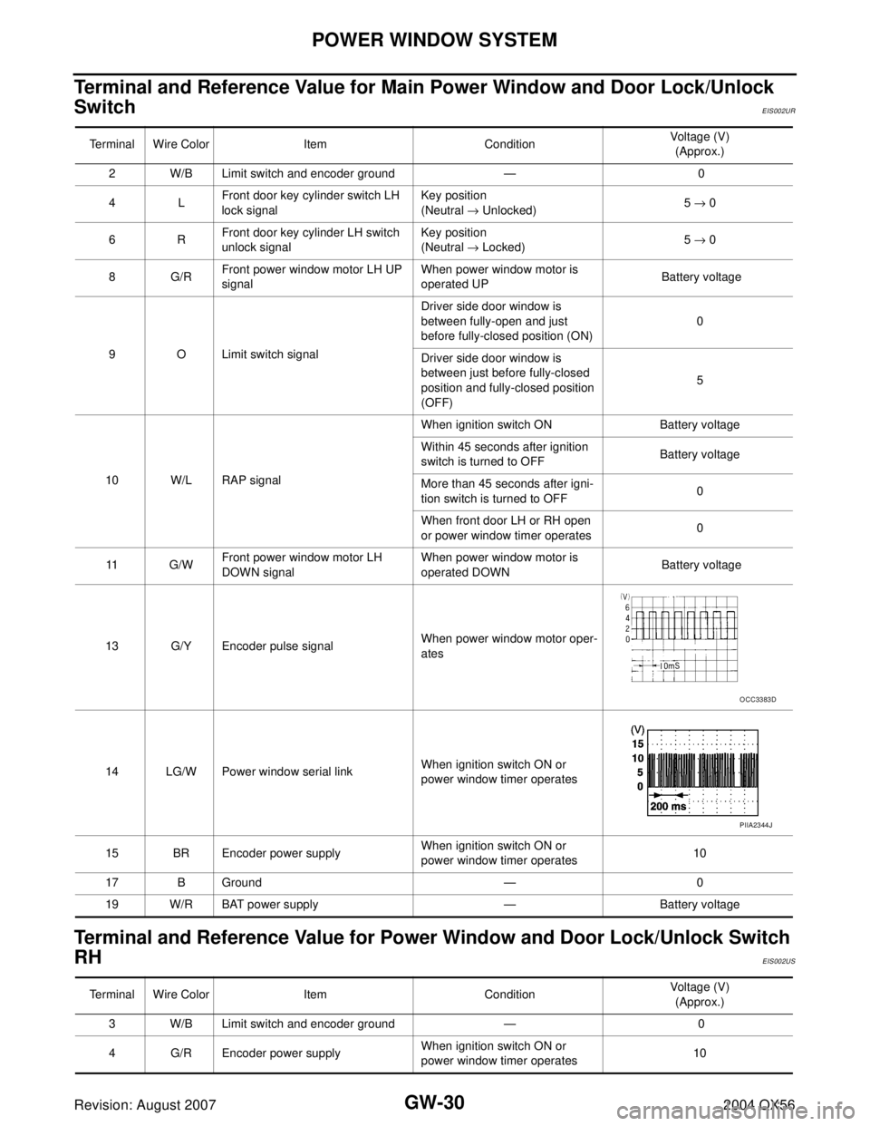
Terminal and Reference Value for Main Power Window and Door Lock/Unlock
Switch
EIS002UR
Terminal and Reference Value for Power Window and Door Lock/Unlock Switch
RH
EIS002US
Terminal Wire Color Item ConditionVoltage (V)
(Approx.)
2 W/B Limit switch and encoder ground — 0
4LFront door key cylinder switch LH
lock signalKey position
(Neutral → Unlocked)5 → 0
6RFront door key cylinder LH switch
unlock signalKey position
(Neutral → Locked)5 → 0
8G/RFront power window motor LH UP
signalWhen power window motor is
operated UP Battery voltage
9 O Limit switch signalDriver side door window is
between fully-open and just
before fully-closed position (ON)0
Driver side door window is
between just before fully-closed
position and fully-closed position
(OFF)5
10 W/L RAP signalWhen ignition switch ON Battery voltage
Within 45 seconds after ignition
switch is turned to OFFBattery voltage
More than 45 seconds after igni-
tion switch is turned to OFF0
When front door LH or RH open
or power window timer operates0
11 G / WFront power window motor LH
DOWN signalWhen power window motor is
operated DOWN Battery voltage
13 G/Y Encoder pulse signalWhen power window motor oper-
ates
14 LG/W Power window serial linkWhen ignition switch ON or
power window timer operates
15 BR Encoder power supplyWhen ignition switch ON or
power window timer operates10
17 B Ground — 0
19 W/R BAT power supply — Battery voltage
OCC3383D
PIIA2344J
Terminal Wire Color Item ConditionVoltage (V)
(Approx.)
3 W/B Limit switch and encoder ground — 0
4 G/R Encoder power supplyWhen ignition switch ON or
power window timer operates10
Page 2166 of 3371
POWER WINDOW SYSTEM
GW-31
C
D
E
F
G
H
J
K
L
MA
B
GW
Revision: August 20072004 QX56
8LFront power window motor RH UP
signalWhen power window motor is
operated UP Battery voltage
9GFront power window motor RH
DOWN signalWhen power window motor is
operated DOWN Battery voltage
10 W/R BAT power supply — Battery voltage
11 B G r o u n d — 0
12 G/Y Encoder pulse signalWhen power window motor oper-
ates
15 G/W Limit switch signalPassenger side door window is
between fully-open and just
before fully-closed position (ON)0
Passenger side door window is
between just before fully-closed
position and fully-closed position
(OFF)5
16 LG/W Power window serial linkWhen ignition switch is ON or
power window timer operating Terminal Wire Color Item ConditionVoltage (V)
(Approx.)
OCC3383D
PIIA2344J
Page 2167 of 3371
GW-32
POWER WINDOW SYSTEM
Revision: August 20072004 QX56
Terminal and Reference Value for BCMEIS002UT
Terminal Wire Color Item ConditionVoltage (V)
(Approx.)
11 O Ignition switch (ACC or ON) Ignition switch
(ACC or ON position)Battery voltage
12 R/L Front door switch RH signalON (Open) Battery voltage
OFF (Close) 0
22 W/V Power window serial linkWhen ignition switch ON or
power window timer operates
38 W/L Ignition switch (ON or START) Ignition switch
(ON or START position)Battery voltage
47 SB Front door switch LH signalON (Open) Battery voltage
OFF (Close) 0
67 B Ground — 0
68 W/L RAP signalWhen ignition switch ON Battery voltage
Within 45 seconds after ignition
switch is turned to OFFBattery voltage
More than 45 seconds after igni-
tion switch is turned to OFF0
When front door LH or RH is
open or power window timer
operates0
69 W/R Power window power supply — Battery voltage
70 W/B BAT power supply — Battery voltage
PIIA2344J
Page 2168 of 3371

POWER WINDOW SYSTEM
GW-33
C
D
E
F
G
H
J
K
L
MA
B
GW
Revision: August 20072004 QX56
Work FlowEIS002UU
1. Check the symptom and customer's requests.
2. Understand the outline of system. Refer to GW-15, "
System Description" .
3. According to the trouble diagnosis chart, repair or replace the cause of the malfunction.
Refer to GW-36, "
Trouble Diagnoses Symptom Chart" .
4. Does power window system operate normally? Yes, GO TO 5, If No, GO TO 3.
5. INSPECTION END.
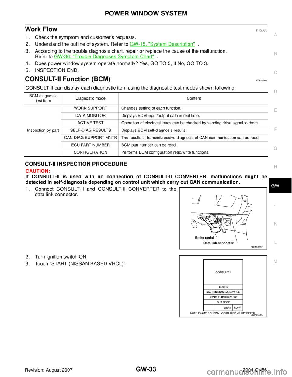
CONSULT-II Function (BCM)EIS002UV
CONSULT-II can display each diagnostic item using the diagnostic test modes shown following.
CONSULT-II INSPECTION PROCEDURE
CAUTION:
If CONSULT-II is used with no connection of CONSULT-II CONVERTER, malfunctions might be
detected in self-diagnosis depending on control unit which carry out CAN communication.
1. Connect CONSULT-II and CONSULT-II CONVERTER to the
data link connector.
2. Turn ignition switch ON.
3. Touch “START (NISSAN BASED VHCL)”.
BCM diagnostic
test itemDiagnostic mode Content
Inspection by partWORK SUPPORT Changes setting of each function.
DATA MONITOR Displays BCM input/output data in real time.
ACTIVE TEST Operation of electrical loads can be checked by sending drive signal to them.
SELF-DIAG RESULTS Displays BCM self-diagnosis results.
CAN DIAG SUPPORT MNTR The results of transmit/receive diagnosis of CAN communication can be read.
ECU PART NUMBER BCM part number can be read.
CONFIGURATION Performs BCM configuration read/write functions.
BBIA0369E
BCIA0029E