Page 1425 of 3371

EC-234Revision: August 2007
DTC P0182, P0183 FTT SENSOR
2004 QX56
4. DETECT MALFUNCTIONING PART
Check the following.
�Harness connectors C1, E41
�Harness for open or short between ECM and “fuel level sensor unit and fuel pump”
>> Repair harness or connector.
5. CHECK FUEL TANK TEMPERATURE SENSOR GROUND CIRCUIT FOR OPEN AND SHORT
1. Turn ignition switch OFF.
2. Disconnect combination meter harness connector.
3. Check harness continuity between “fuel level sensor unit and fuel pump” terminal 5 and combination
meter terminal 16. Refer to Wiring Diagram.
4. Also check harness for short to ground and short to power.
OK or NG
OK >> GO TO 7.
NG >> GO TO 6.
6. DETECT MALFUNCTIONING PART
Check the following.
�Harness connectors C1, E41
�Harness connectors E152, M31
�Harness for open or short between “fuel level sensor unit and fuel pump” and combination meter
>> Repair open circuit or short to ground or short to power in harness or connector.
7. CHECK FUEL TANK TEMPERATURE SENSOR
Refer to EC-234, "
Component Inspection" .
OK or NG
OK >> GO TO 8.
NG >> Replace fuel level sensor unit.
8. CHECK INTERMITTENT INCIDENT
Refer to EC-127, "
TROUBLE DIAGNOSIS FOR INTERMITTENT INCIDENT" .
>>INSPECTION END
Component InspectionUBS00H3G
FUEL TANK TEMPERATURE SENSOR
1. Remove fuel level sensor unit.Continuity should exist.
Page 1426 of 3371
DTC P0182, P0183 FTT SENSOR
EC-235
C
D
E
F
G
H
I
J
K
L
MA
EC
Revision: August 20072004 QX56
2. Check resistance between “fuel level sensor unit and fuel pump”
terminals 4 and 5 by heating with hot water or heat gun as
shown in the figure.
Removal and InstallationUBS00H3H
FUEL TANK TEMPERATURE SENSOR
Refer to FL-5, "FUEL LEVEL SENSOR UNIT, FUEL FILTER AND FUEL PUMP ASSEMBLY" .
Temperature °C (°F) Resistance kΩ
20 (68) 2.3 - 2.7
50 (122) 0.79 - 0.90
PBIB0931E
Page 1438 of 3371
DTC P0300 - P0308 MULTIPLE CYLINDER MISFIRE, NO. 1 - 8 CYLINDER MIS-
FIRE
EC-247
C
D
E
F
G
H
I
J
K
L
MA
EC
Revision: August 20072004 QX56
8. CHECK FUEL PRESSURE
1. Install all removed parts.
2. Release fuel pressure to zero. Refer to EC-46, "
FUEL PRESSURE RELEASE" .
3. Install fuel pressure gauge and check fuel pressure. Refer to EC-47, "
FUEL PRESSURE CHECK" .
OK or NG
OK >> GO TO 10.
NG >> GO TO 9.
9. DETECT MALFUNCTIONING PART
Check the following.
�Fuel pump and circuit (Refer to EC-601, "FUEL PUMP CIRCUIT" .)
�Fuel pressure regulator (Refer to EC-47, "FUEL PRESSURE CHECK" .)
�Fuel lines
�Fuel filter for clogging
>> Repair or replace.
10. CHECK IGNITION TIMING
Check the following items. Refer to EC-79, "
Basic Inspection" .
OK or NG
OK >> GO TO 11.
NG >> Follow the EC-79, "
Basic Inspection" . At idle: Approx. 350 kPa (3.57 kg/cm
2 , 51
psi)
Items Specifications
Target idle speed 650 ± 50 rpm (in P or N position)
Ignition timing 15 ± 5° BTDC (in P or N position)
Page 1510 of 3371

DTC P0455 EVAP CONTROL SYSTEM
EC-319
C
D
E
F
G
H
I
J
K
L
MA
EC
Revision: August 20072004 QX56
5. CHECK EVAP PURGE LINE
Check EVAP purge line (pipe, rubber tube, fuel tank and EVAP canister) for cracks, improper connection or
disconnection.
Refer to EC-634, "
EVAPORATIVE EMISSION LINE DRAWING" .
OK or NG
OK >> GO TO 6.
NG >> Repair or reconnect the hose.
6. CLEAN EVAP PURGE LINE
Clean EVAP purge line (pipe and rubber tube) using air blower.
>> GO TO 7.
7. CHECK EVAP CANISTER VENT CONTROL VALVE
Check the following.
�EVAP canister vent control valve is installed properly.
Refer to EC-637, "
Removal and Installation" .
�EVAP canister vent control valve.
Refer to EC-297, "
Component Inspection" .
OK or NG
OK >> GO TO 8.
NG >> Repair or replace EVAP canister vent control valve and O-ring.
8. INSTALL THE PRESSURE PUMP
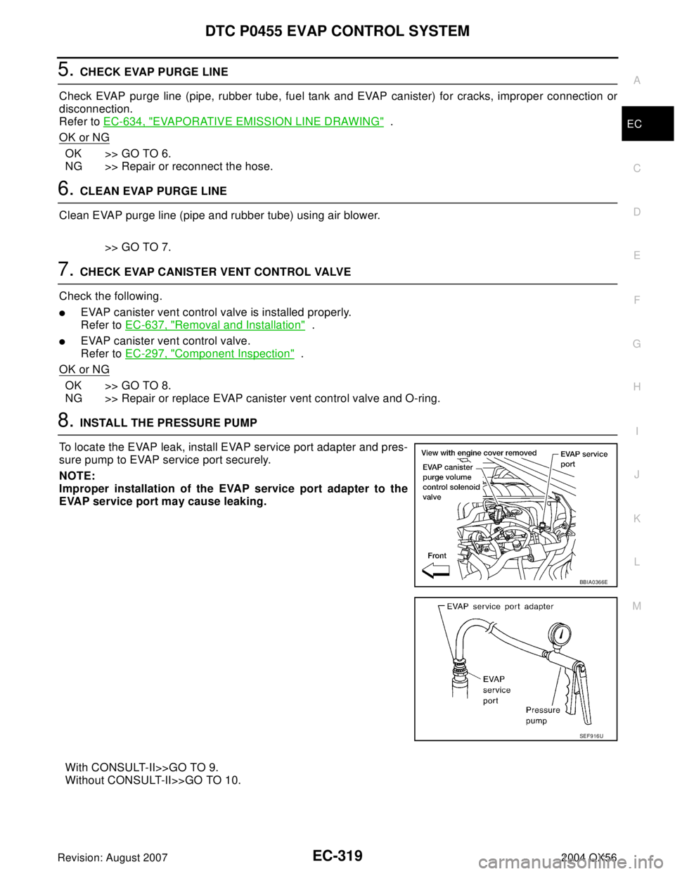
To locate the EVAP leak, install EVAP service port adapter and pres-
sure pump to EVAP service port securely.
NOTE:
Improper installation of the EVAP service port adapter to the
EVAP service port may cause leaking.
With CONSULT-II>>GO TO 9.
Without CONSULT-II>>GO TO 10.
BBIA0366E
SEF 9 16 U
Page 1526 of 3371
DTC P0460 FUEL LEVEL SENSOR
EC-335
C
D
E
F
G
H
I
J
K
L
MA
EC
Revision: August 20072004 QX56
Diagnostic ProcedureUBS00H60
1. CHECK DTC WITH COMBINATION METER
Refer to DI-5, "
COMBINATION METERS" .
OK or NG
OK >> GO TO 2.
NG >> Go to DI-22, "
Fuel Level Sensor Unit Inspection" .
2. CHECK INTERMITTENT INCIDENT
Refer to EC-127, "
TROUBLE DIAGNOSIS FOR INTERMITTENT INCIDENT" .
>>INSPECTION END
Removal and InstallationUBS00H61
FUEL LEVEL SENSOR
Refer to FL-5, "FUEL LEVEL SENSOR UNIT, FUEL FILTER AND FUEL PUMP ASSEMBLY" .
Page 1528 of 3371

DTC P0461 FUEL LEVEL SENSOR
EC-337
C
D
E
F
G
H
I
J
K
L
MA
EC
Revision: August 20072004 QX56
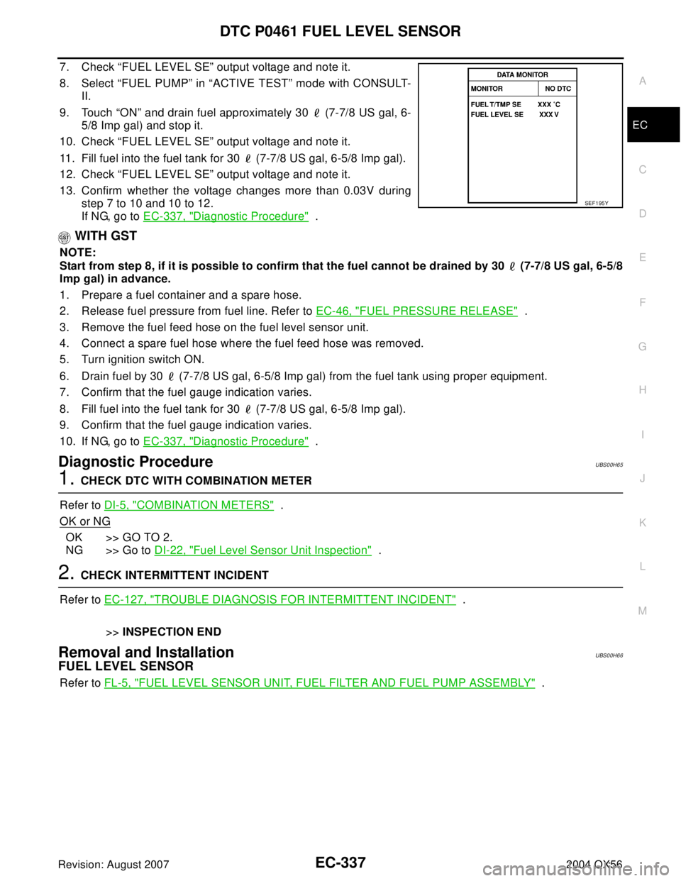
7. Check “FUEL LEVEL SE” output voltage and note it.
8. Select “FUEL PUMP” in “ACTIVE TEST” mode with CONSULT-
II.
9. Touch “ON” and drain fuel approximately 30 (7-7/8 US gal, 6-
5/8 Imp gal) and stop it.
10. Check “FUEL LEVEL SE” output voltage and note it.
11. Fill fuel into the fuel tank for 30 (7-7/8 US gal, 6-5/8 Imp gal).
12. Check “FUEL LEVEL SE” output voltage and note it.
13. Confirm whether the voltage changes more than 0.03V during
step 7 to 10 and 10 to 12.
If NG, go to EC-337, "
Diagnostic Procedure" .
WITH GST
NOTE:
Start from step 8, if it is possible to confirm that the fuel cannot be drained by 30 (7-7/8 US gal, 6-5/8
Imp gal) in advance.
1. Prepare a fuel container and a spare hose.
2. Release fuel pressure from fuel line. Refer to EC-46, "
FUEL PRESSURE RELEASE" .
3. Remove the fuel feed hose on the fuel level sensor unit.
4. Connect a spare fuel hose where the fuel feed hose was removed.
5. Turn ignition switch ON.
6. Drain fuel by 30 (7-7/8 US gal, 6-5/8 Imp gal) from the fuel tank using proper equipment.
7. Confirm that the fuel gauge indication varies.
8. Fill fuel into the fuel tank for 30 (7-7/8 US gal, 6-5/8 Imp gal).
9. Confirm that the fuel gauge indication varies.
10. If NG, go to EC-337, "
Diagnostic Procedure" .
Diagnostic ProcedureUBS00H65
1. CHECK DTC WITH COMBINATION METER
Refer to DI-5, "
COMBINATION METERS" .
OK or NG
OK >> GO TO 2.
NG >> Go to DI-22, "
Fuel Level Sensor Unit Inspection" .
2. CHECK INTERMITTENT INCIDENT
Refer to EC-127, "
TROUBLE DIAGNOSIS FOR INTERMITTENT INCIDENT" .
>>INSPECTION END
Removal and InstallationUBS00H66
FUEL LEVEL SENSOR
Refer to FL-5, "FUEL LEVEL SENSOR UNIT, FUEL FILTER AND FUEL PUMP ASSEMBLY" .
SEF 1 95 Y
Page 1530 of 3371
DTC P0462, P0463 FUEL LEVEL SENSOR CIRCUIT
EC-339
C
D
E
F
G
H
I
J
K
L
MA
EC
Revision: August 20072004 QX56
Diagnostic ProcedureUBS00H6A
1. CHECK DTC WITH COMBINATION METER
Refer to DI-5, "
COMBINATION METERS" .
OK or NG
OK >> GO TO 2.
NG >> Go to DI-22, "
Fuel Level Sensor Unit Inspection" .
2. CHECK INTERMITTENT INCIDENT
Refer to EC-127, "
TROUBLE DIAGNOSIS FOR INTERMITTENT INCIDENT" .
>>INSPECTION END
Removal and InstallationUBS00H6B
FUEL LEVEL SENSOR
Refer to FL-5, "FUEL LEVEL SENSOR UNIT, FUEL FILTER AND FUEL PUMP ASSEMBLY" .
Page 1620 of 3371

DTC P1271, P1281 A/F SENSOR 1
EC-429
C
D
E
F
G
H
I
J
K
L
MA
EC
Revision: August 20072004 QX56
DTC P1271, P1281 A/F SENSOR 1PFP:22693
Component DescriptionUBS00H9F
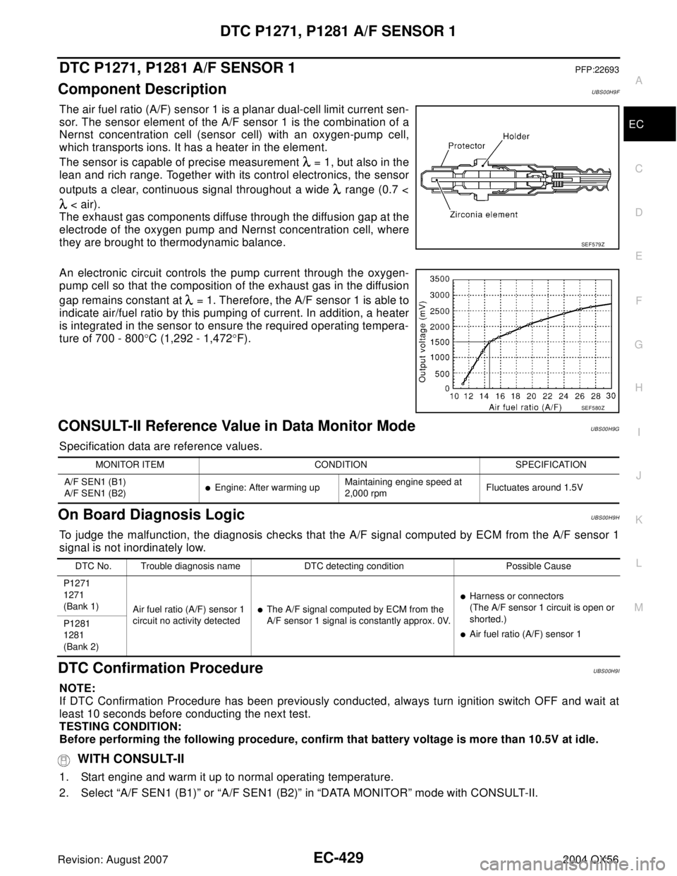
The air fuel ratio (A/F) sensor 1 is a planar dual-cell limit current sen-
sor. The sensor element of the A/F sensor 1 is the combination of a
Nernst concentration cell (sensor cell) with an oxygen-pump cell,
which transports ions. It has a heater in the element.
The sensor is capable of precise measurement = 1, but also in the
lean and rich range. Together with its control electronics, the sensor
outputs a clear, continuous signal throughout a wide range (0.7 <
< air).
The exhaust gas components diffuse through the diffusion gap at the
electrode of the oxygen pump and Nernst concentration cell, where
they are brought to thermodynamic balance.
An electronic circuit controls the pump current through the oxygen-
pump cell so that the composition of the exhaust gas in the diffusion
gap remains constant at = 1. Therefore, the A/F sensor 1 is able to
indicate air/fuel ratio by this pumping of current. In addition, a heater
is integrated in the sensor to ensure the required operating tempera-
ture of 700 - 800°C (1,292 - 1,472°F).
CONSULT-II Reference Value in Data Monitor ModeUBS00H9G
Specification data are reference values.
On Board Diagnosis LogicUBS00H9H
To judge the malfunction, the diagnosis checks that the A/F signal computed by ECM from the A/F sensor 1
signal is not inordinately low.
DTC Confirmation ProcedureUBS00H9I
NOTE:
If DTC Confirmation Procedure has been previously conducted, always turn ignition switch OFF and wait at
least 10 seconds before conducting the next test.
TESTING CONDITION:
Before performing the following procedure, confirm that battery voltage is more than 10.5V at idle.
WITH CONSULT-II
1. Start engine and warm it up to normal operating temperature.
2. Select “A/F SEN1 (B1)” or “A/F SEN1 (B2)” in “DATA MONITOR” mode with CONSULT-II.
SEF 5 79 Z
SEF 5 80 Z
MONITOR ITEM CONDITION SPECIFICATION
A/F SEN1 (B1)
A/F SEN1 (B2)
�Engine: After warming upMaintaining engine speed at
2,000 rpmFluctuates around 1.5V
DTC No. Trouble diagnosis name DTC detecting condition Possible Cause
P1271
1271
(Bank 1)
Air fuel ratio (A/F) sensor 1
circuit no activity detected
�The A/F signal computed by ECM from the
A/F sensor 1 signal is constantly approx. 0V.
�Harness or connectors
(The A/F sensor 1 circuit is open or
shorted.)
�Air fuel ratio (A/F) sensor 1 P1281
1281
(Bank 2)